Design procedure, Table 4. operating modes – Rainbow Electronics MAX1637 User Manual
Page 14
MAX1637
Miniature, Low-Voltage,
Precision Step-Down Controller
14
______________________________________________________________________________________
make prototype troubleshooting difficult since only
20ms or 30ms elapse before the SMPS is latched off.
The overvoltage crowbar protection is disabled in out-
put undervoltage mode.
Output Overvoltage Protection
The overvoltage crowbar-protection circuit is intended
to blow a fuse in series with the battery if the main
SMPS output rises significantly higher than its standard
level (Table 4). In normal operation, the output is com-
pared to the internal precision reference voltage. If the
output goes 7% above nominal, the synchronous-recti-
fier MOSFET turns on 100% (the high-side MOSFET is
simultaneously forced off) in order to draw massive
amounts of battery current to blow the fuse. This safety
feature does not protect the system against a failure of
the controller IC itself, but is intended primarily to guard
against a short across the high-side MOSFET. A crow-
bar event is latched and can only be reset by a rising
edge on SHDN (or by removal of the V
CC
supply volt-
age). The overvoltage-detection decision is made rela-
tive to the regulation point.
Internal Digital Soft-Start Circuit
Soft-start allows a gradual increase of the internal cur-
rent-limit level at start-up to reduce input surge cur-
rents. The SMPS contains an internal digital soft-start
circuit controlled by a counter, a digital-to-analog con-
verter (DAC), and a current-limit comparator. In shut-
down, the soft-start counter is reset to zero. When the
SMPS is enabled, its counter starts counting oscillator
pulses, and the DAC begins incrementing the compari-
son voltage applied to the current-limit comparator. The
DAC output increases from 0mV to 100mV in five equal
steps as the count increases to 512 clocks. As a result,
the main output capacitor charges up relatively slowly.
The exact time of the output rise depends on output
capacitance and load current, but it is typically 1ms
with a 300kHz oscillator.
Setting the Output Voltage
The output voltage is set via a resistor divider connect-
ed to FB (Figure 1). Calculate the output voltage with
the following formula:
V
OUT
= V
REF
(1 + R2 / R3)
where V
REF
= 1.1V nominal.
Recommended normal values for R3 range from 5k
Ω
to
100k
Ω
. To achieve a 1.1V nominal output, connect FB
directly to CSL. Remote output voltage sensing is pos-
sible by using the top of the external resistor divider as
the remote sense point.
__________________Design Procedure
The standard application circuit (Figure 1) contains a
ready-to-use solution for common application needs.
Use the following design procedure to optimize the
basic schematic for different voltage or current require-
ments. But before beginning a design, firmly establish
the following:
•
Maximum input (battery) voltage, V
IN(MAX)
. This
value should include the worst-case conditions, such
as no-load operation when a battery charger or AC
adapter is connected but no battery is installed.
V
IN(MAX)
must not exceed 30V.
•
Minimum input (battery) voltage, V
IN(MIN)
. This value
should be taken at full load under the lowest battery
conditions. If the minimum input-output difference is
less than 1.5V, the filter capacitance required to
maintain good AC load regulation increases (see
Low-Voltage Operation
section).
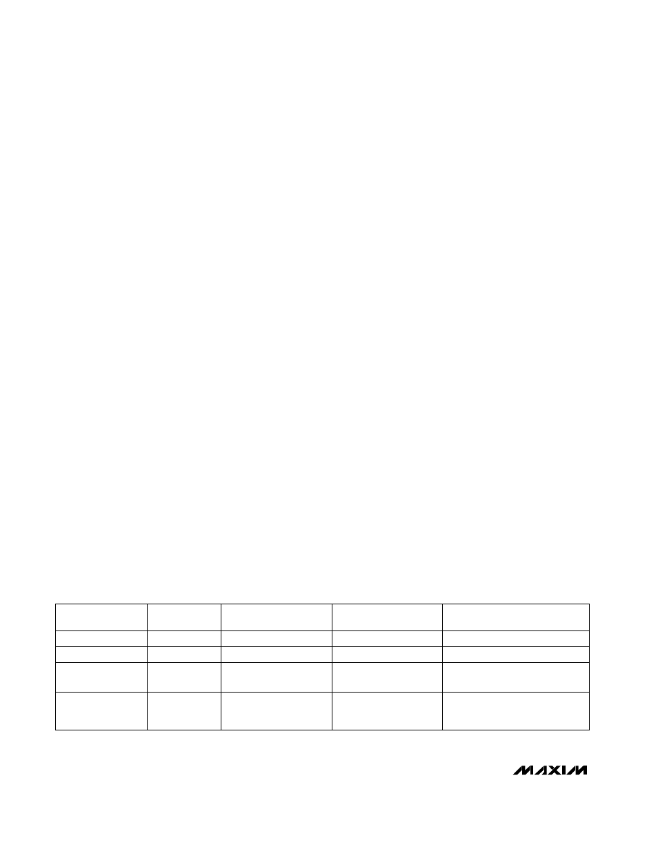
Table 4. Operating Modes
All circuit blocks off
Low
Shutdown
REF = off, DL = low
High
Output
Undervoltage
Lockout
REF = off, DL = high
High
Overvoltage
(Crowbar)
—
V
OUT
below 70% of
nominal after 20ms to
30ms timeout expires
V
OUT
greater than 7%
above regulation point
V
OUT
in regulation
CONDITIONS
MODE
All circuit blocks active
High
Run
STATUS
SHDN
Lowest current consumption
Rising edge on SHDN exits
UVLO
Rising edge on SHDN exits
crowbar
Normal operation
NOTES