Rainbow Electronics MAX1637 User Manual
Page 13
MAX1637
Miniature, Low-Voltage,
Precision Step-Down Controller
______________________________________________________________________________________
13
For prototyping or for very high-current applications, it
may be useful to wire the current-sense inputs with a
twisted pair rather than PC traces (two pieces of
wrapped wire twisted together are sufficient). This
reduces the noise picked up at CSH and CSL, which can
cause unstable switching and reduced output current.
Oscillator Frequency
and Synchronization (SYNC)
The SYNC input controls the oscillator frequency as fol-
lows: low selects 200kHz, high selects 300kHz. SYNC
can also be used to synchronize with an external 5V
CMOS or TTL clock generator. It has a guaranteed
240kHz to 340kHz capture range. A high-to-low transi-
tion on SYNC initiates a new cycle.
Operation at 300kHz optimizes the application circuit
for component size and cost. Operation at 200kHz
increases efficiency, reduces dropout, and improves
load-transient response at low input-output voltage dif-
ferences (see the
Low-Voltage Operation
section).
Output Voltage Accuracy (CC)
Output voltage error is guaranteed to be within ±2%
over all conditions of line, load, and temperature. The
MAX1637’s DC load regulation is typically better than
0.1%, due to its integrator amplifier. The device opti-
mizes transient response by providing a feedback sig-
nal with a direct path from the output to the main
summing PWM comparator. The integrated feedback
signal from the CC transconductance amplifier is also
summed into the PWM comparator, with the gain
weighted so that the signal has only enough gain to
correct the DC inaccuracies. The integrator’s response
time is determined by the time constant set by the
capacitor placed on the CC pin. The time constant
should neither be so fast that the integrator responds to
the normal V
OUT
ripple, nor too slow to negate the inte-
grator’s effect. A 470pF to 1500pF CC capacitor is suf-
ficient for 200kHz to 300kHz frequencies.
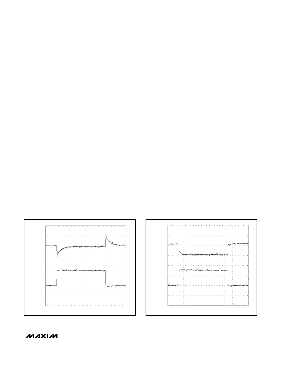
Figure 6 shows the output voltage response to a 0A to
3A load transient with and without the integrator. With
the integrator, the output voltage returns to within 0.1%
of its no-load value with only a small AC excursion.
Without the integrator, load regulation is degraded
(Figure 6b). Asymmetrical clamping at the integrator
output prevents worsening of load transients during
pulse-skipping mode.
Output Undervoltage Lockout
The output undervoltage-lockout circuit protects
against heavy overloads and short-circuits at the main
SMPS output. This scheme employs a timer rather than
a foldback current limit. The SMPS has an undervolt-
age-protection circuit, which is activated 6144 clock
cycles after the SMPS is enabled. If the SMPS output is
under 70% of the nominal value, it is latched off and
does not restart until SHDN is toggled. Applications
that use the recommended RC power-on-reset circuit
will also clear the fault condition when V
CC
falls below
0.5V (typical). Note that undervoltage protection can
0
2
4
-50
50
I
OUT
(A)
V
OUT
(mV)
(100
µ
s/div)
CC = 470pF
V
OUT
= 3.3V
INTEGRATOR
ACTIVE
Figure 6a. Load-Transient Response with Integrator Active
0
2
4
-50
50
I
OUT
(A)
V
OUT
(mV)
(100
µ
s/div)
CC = REF
V
OUT
= 3.3V
INTEGRATOR
DEACTIVATED
Figure 6b. Load-Transient Response with Integrator
Deactivated