Table 3. skip pwm table – Rainbow Electronics MAX1637 User Manual
Page 11
MAX1637
Miniature, Low-Voltage,
Precision Step-Down Controller
______________________________________________________________________________________
11
Idle Mode
When SKIP is low, idle-mode circuitry automatically
optimizes efficiency throughout the load-current range.
Idle mode dramatically improves light-load efficiency
by reducing the effective frequency, subsequently
reducing switching losses. It forces the peak inductor
current to ramp to 30% of the full current limit, deliver-
ing extra energy to the output and allowing subsequent
cycles to be skipped. Idle mode transitions seamlessly
to fixed-frequency PWM operation as load current
increases (Table 3).
Fixed-Frequency Mode
When SKIP is high, the controller always operates in
fixed-frequency PWM mode for lowest noise. Each pulse
from the oscillator sets the main PWM latch that turns on
the high-side switch for a period determined by the duty
factor (approximately V
OUT
/ V
IN
). As the high-side switch
turns off, the synchronous rectifier latch is set; 60ns later,
the low-side switch turns on. The low-side switch stays on
until the beginning of the next clock cycle.
In PWM mode, the controller operates as a fixed-fre-
quency, current-mode controller in which the duty fac-
tor is set by the input/output voltage ratio. PWM mode
(SKIP = high) forces two changes on the PWM con-
troller. First, it disables the minimum-current compara-
tor, ensuring fixed-frequency operation. Second, it
changes the detection threshold for reverse-current
limit from 0mV to -100mV, allowing the inductor current
to reverse at light loads. This results in fixed-frequency
operation and continuous inductor-current flow. PWM
mode eliminates discontinuous-mode inductor ringing
and improves cross-regulation of transformer-coupled,
multiple-output supplies.
The current-mode feedback system regulates the peak
inductor-current value as a function of the output volt-
age error signal. In continuous-conduction mode, the
average inductor current is nearly the same as the
peak current, so the circuit acts as a switch-mode
transconductance amplifier. This pushes the second
output LC filter pole, normally found in a duty-factor-
controlled (voltage-mode) PWM, to a higher frequency.
To preserve inner-loop stability and eliminate regenera-
tive inductor-current “staircasing,” a slope-compensa-
tion ramp is summed into the main PWM comparator to
make the apparent duty factor less than 50%.
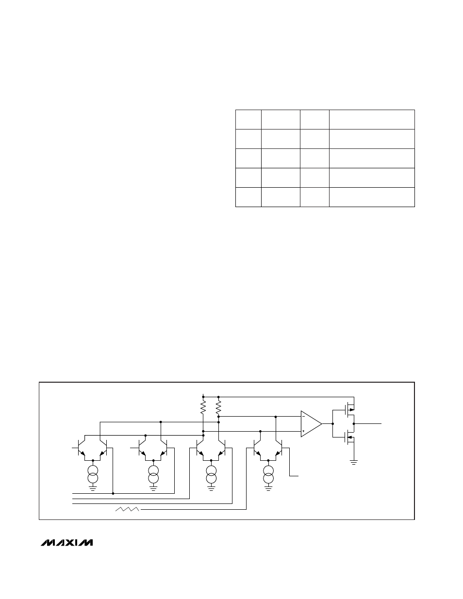
The relative gains of the voltage-sense and current-
sense inputs are weighted by the values of the current
sources that bias four differential input stages in the
main PWM comparator (Figure 4). The voltage sense
into the PWM has been conditioned by an integrated
component of the feedback voltage, yielding excellent
DC output voltage accuracy. See the
Output Voltage
Accuracy
section for details.
Constant frequency PWM,
continuous inductor current
Heavy
Low
Constant frequency PWM,
continuous inductor current
Heavy
High
Constant frequency PWM,
continuous inductor current
Light
High
SKIP
Pulse-skipping, discontin-
uous inductor current
Light
Low
DESCRIPTION
LOAD
CURRENT
Table 3.
SKIP
PWM Table
PWM
PWM
PWM
Idle
MODE
FB
REF
CSH
CSL
CC
SLOPE COMPENSATION
V
CC
I2
R1
R2
TO PWM
LOGIC
OUTPUT DRIVER
UNCOMPENSATED
HIGH-SPEED
LEVEL TRANSLATOR
AND BUFFER
I1
I3
I4
V
BIAS
Figure 4. Main PWM Comparator Functional Diagram