Rainbow Electronics MAX1637 User Manual
Page 19
sensing at the supply’s output terminals without interfer-
ence from IR drops and ground noise. Other high-cur-
rent paths should also be minimized, but focusing
primarily on short ground and current-sense connec-
tions eliminates about 90% of all PC board layout prob-
lems (see the PC board layouts in the MAX1637
evaluation kit manual for examples).
2) Place the IC and signal components. Keep the main
switching nodes (LX nodes) away from sensitive
analog components (current-sense traces and REF
capacitor). Place the IC and analog components on
the opposite side of the board from the power-
switching node.
Important
: The IC must be no fur-
ther than 10mm from the current-sense resistors.
Keep the gate-drive traces (DH, DL, and BST) short-
er than 20mm and route them away from CSH, CSL,
and REF. Place ceramic bypass capacitors close to
the IC. The bulk capacitors can be placed further
away.
3) Use a single-point star ground where the input
ground trace, power ground (subground plane), and
normal ground plane meet at the supply's output
ground terminal. Connect both IC ground pins and
all IC bypass capacitors to the normal ground plane.
MAX1637
Miniature, Low-Voltage,
Precision Step-Down Controller
______________________________________________________________________________________
19
MAX1637
SENSE RESISTOR
HIGH-CURRENT PATH
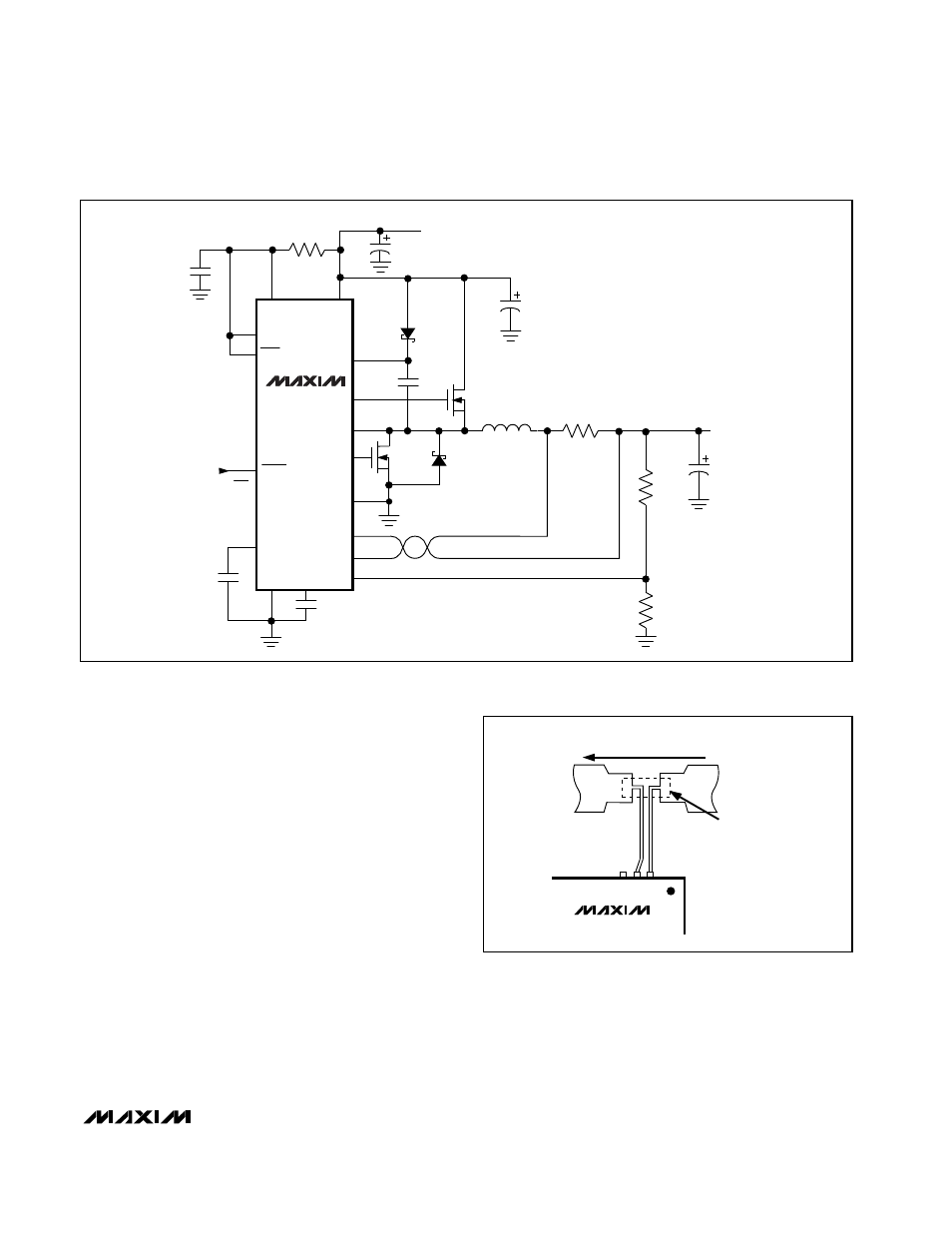
Figure 8. Kelvin Connections for the Current-Sense Resistors
MAX1637
0.1
µ
F
1
µ
F
IRF7401
CMPSH-3
IRF7401
1
µ
F
470pF
MBRS130
470
µ
F
LOW ESR
TANTALUM
4.7
µ
F
TANTALUM
220
µ
F
OS-CON
V
BIAS
10
µ
H
CDHR125-100
20m
Ω
1%
130k
1%
100k
1%
OUTPUT = 2.5V AT 4A
V
CC
20
Ω
GND
CC
DL
LX
DH
BST
V
GG
CSH
CSL
FB
SHDN
ON/OFF
SKIP
SYNC
REF
PGND
3.15V TO 5.5V
Figure 7. 3.15V to 5.5V Single-Supply Application Circuit