Pin description – Rainbow Electronics MAX1844 User Manual
Page 8
MAX1844
High-Speed Step-Down Controller with
Accurate Current Limit for Notebook Computers
8
_______________________________________________________________________________________
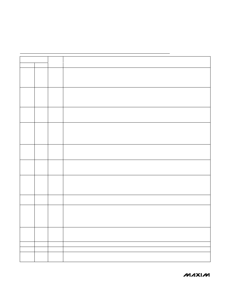
PIN
QSOP
QFN
NAME
FUNCTION
1
18
CS
Current-Sense Input. Connect a low-value current-sense resistor between CS and GND for accurate
current sensing. For lower power dissipation (less accurate) current sensing, connect CS to LX to
use the synchronous rectifier as the sense resistor. The PWM controller will not begin a cycle unless
the current sensed at CS is less than the current-limit threshold programmed at ILIM.
2
19
LATCH
Overvoltage Protection Latch Control Input. The synchronous rectifier MOSFET is always forced to
the on state when an overvoltage fault is detected. If LATCH is low, the synchronous rectifier remains
on until either OVP is brought high, SHDN is toggled, or V
CC
is cycled below 1V. If LATCH is high,
normal operation resumes when the overvoltage condition ends.
3
20
SHDN
Shutdown Control Input. Drive SHDN to GND to force the MAX1844 into shutdown. Drive or connect
to V
CC
for normal operation. A rising edge on SHDN clears the overvoltage and undervoltage
protection fault latches.
4
1
OVP
Overvoltage Protection Control Input. An overvoltage fault occurs if the internal or external feedback
voltage exceeds the voltage at OVP. Apply a voltage between 1V and 1.8V to set the overvoltage
limit between 100% and 180% of nominal output voltage. Connect to GND to assert the default
overvoltage limit at 114% of the nominal output voltage. Connect to V
CC
to disable overvoltage fault
detection and clear the overvoltage protection fault latch.
5
2
FB
Feedback Input. Connect to V
CC
for a 1.8V fixed output or to GND for a 2.5V fixed output. For an
adjustable output (1V to 5.5V), connect FB to a resistive-divider from the output voltage. The FB
regulation level is 1V.
6
3
OUT
Output Voltage Sense Connection. Connect directly to the junction of the external output filter
capacitors. OUT senses the output voltage to determine the on-time for the high-side switching
MOSFET. OUT also serves as the feedback input in fixed-output modes.
7
4
ILIM
Current-Limit Threshold Adjustment. The current-limit threshold at CS is 0.1 times the voltage at ILIM.
Connect ILIM to a resistive-divider (typically from REF) to set the current-limit threshold between
25mV and 300mV (with 0.25V to 3V at ILIM). Connect to V
CC
to assert the 100mV default current-limit
threshold.
8
5
REF
2V Reference Voltage Output. Bypass to GND with a 0.22µF (min) bypass capacitor. Can supply
50µA for external loads. Reference turns off in shutdown.
9
6
UVP
Undervoltage Protection Control Input. An undervoltage fault occurs if the internal or external
feedback voltage is less than the voltage at UVP. Apply a voltage between 0.4V and 1V to set the
undervoltage limit between 40% and 100% of the nominal output voltage. Connect to V
CC
to assert
the default undervoltage limit of 70% of the nominal output voltage. Connect to GND to disable
undervoltage fault detection and clear the undervoltage protection latch.
10
7
PGOOD
Power-Good Open-Drain Output. PGOOD is low when the output voltage is more than 10% above or
below the normal regulation point or during soft-start. PGOOD is high impedance when the output is
in regulation and the soft-start circuit has terminated. PGOOD is low in shutdown.
11
8
GND
Analog and Power Ground
12
9
DL
Synchronous Rectifier Gate-Driver Output. Swings from GND to V
DD
.
13
10
V
DD
Supply Input for the DL Gate Drive. Connect to the system supply voltage, 4.5V to 5.5V. Bypass to
GND with a 1µF (min) ceramic capacitor.
Pin Description