Rainbow Electronics MAX1844 User Manual
Page 17
The amount of output sag is also a function of the maxi-
mum duty factor, which can be calculated from the on-
time and minimum off-time:
where
and minimum off-time = 400ns (typ) (see Table 5 for K
values).
The amount of overshoot during a full-load to no-load
transient due to stored inductor energy can be calculated
as:
Setting the Current Limit
For most applications, set the MAX1844 current limit by
the following procedure:
1) Determine the minimum (valley) inductor current
I
L(MIN)
under conditions when V
IN
is small, V
OUT
is
large, and load current is maximum. The minimum
inductor current is I
LOAD
minus half the ripple cur-
rent (Figure 4).
2) The sense resistor determines the achievable
current-limit accuracy. There is a trade-off between
current-limit accuracy and sense-resistor power dis-
sipation. Most applications employ a current-sense
voltage of 50mV to 100mV. Choose a sense resistor
so that:
R
SENSE
= CS Threshold Voltage / I
L(MIN)
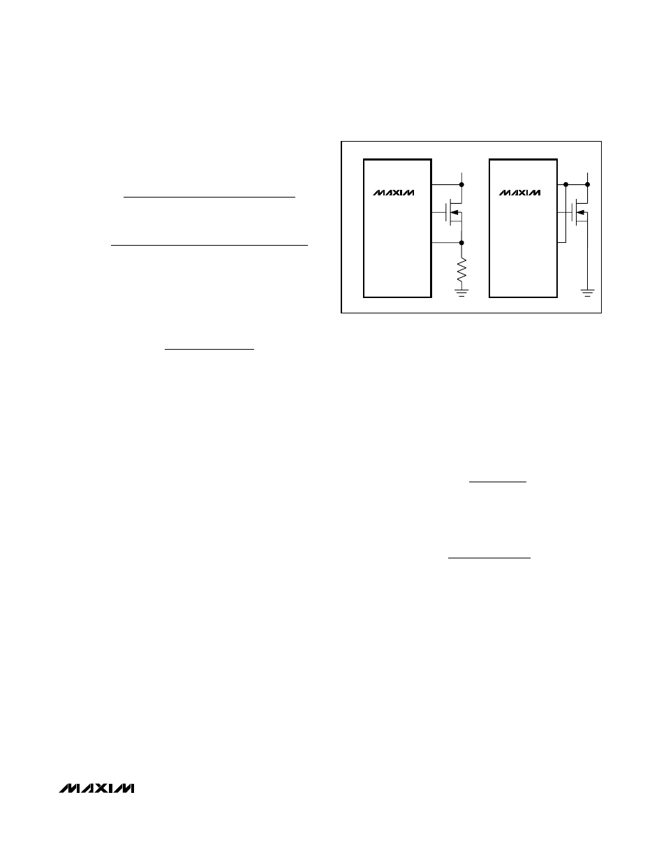
Extremely cost-sensitive applications that do not
require high-accuracy current sensing can use the on-
resistance of the low-side MOSFET switch in place of
the sense resistor by connecting CS to LX (Figure 8b).
Use the worst-case value for R
DS(ON)
from the MOSFET
Q2 data sheet, and add a margin of 0.5%/°C for the
rise in R
DS(ON)
with temperature. Then use that
R
DS(ON)
value and I
L(MIN)
from step 1 above to deter-
mine the CS threshold voltage. If the default 100mV
threshold is unacceptable, set the value as in step 2
above.
In all cases, ensure an acceptable CS threshold volt-
age despite inaccuracies in resistor values.
Output Capacitor Selection
The output filter capacitor must have low enough effective
series resistance (ESR) to meet output ripple and load-
transient requirements, yet have high enough ESR to sat-
isfy stability requirements.
For CPU core voltage converters and other applications
where the output is subject to violent load transients, the
output capacitor’s size depends on how much ESR is
needed to prevent the output from dipping too low under
a load transient. Ignoring the sag due to finite capaci-
tance:
In non-CPU applications, the output capacitor’s size often
depends on how much ESR is needed to maintain an
acceptable level of output voltage ripple:
The actual microfarad capacitance value required relates
to the physical size needed to achieve low ESR, as well
as to the chemistry of the capacitor technology. Thus, the
capacitor is usually selected by ESR and voltage rating
rather than by capacitance value (this is true of tantalums,
OS-CONs, and other electrolytics).
When using low-capacity filter capacitors, such as
ceramic or polymer types, capacitor size is usually deter-
mined by the capacity needed to prevent V
SAG
and
V
SOAR
from causing problems during load transients.
Generally, once enough capacitance is added to meet
the overshoot requirement, undershoot at the rising load
edge is no longer a problem (also, see the V
SAG
and
V
SOAR
equation in the Transient Response section).
R
V
LIR I
ESR
P- P
LOAD(MAX)
≤
×
R
V
I
ESR
DIP
LOAD(MAX)
≤
V
L
I
C
V
SOAR
LOAD MAX
OUT OUT
≈
× ∆
(
)
(
)
2
2
DUTY
K (V
+ 0.075V)/ V
K (V
+ 0.075V)/ V
+ min off - time
OUT IN
OUT OUT
=
V
( I
)
L
2
C
DUTY (V
- V
)
SAG
LOAD(MAX)
2
OUT
IN(MIN)
OUT
=
Ч
Ч
Ч
∆
MAX1844
High-Speed Step-Down Controller with
Accurate Current Limit for Notebook Computers
______________________________________________________________________________________
17
DL
CS
LX
a)
b)
MAX1844
DL
CS
LX
MAX1844
Figure 8. Current-Sense Circuits