Max1844, Table 3. operating mode truth table, Table 4. frequency selection guidelines – Rainbow Electronics MAX1844 User Manual
Page 12
MAX1844
width is inversely proportional to input voltage and directly
proportional to output voltage. Another one-shot sets a
minimum off-time (400ns typ). The on-time one-shot is trig-
gered if the error comparator is low, the low-side switch
current is below the current-limit threshold, and the mini-
mum off-time one-shot has timed out.
On-Time One-Shot (TON)
The heart of the PWM core is the one-shot that sets the
high-side switch on-time. This fast, low-jitter, adjustable
one-shot includes circuitry that varies the on-time in
response to battery and output voltage. The high-side
switch on-time is inversely proportional to the battery
voltage as measured by the V+ input, and proportional
to the output voltage. This algorithm results in a nearly
constant switching frequency despite the lack of a fixed-
frequency clock generator. The benefits of a constant
switching frequency are twofold: first, the frequency can
be selected to avoid noise-sensitive regions such as the
455kHz IF band; second, the inductor ripple-current
operating point remains relatively constant, resulting in
easy design methodology and predictable output volt-
age ripple. The on-time is given by:
On-Time = K (V
OUT
+ 0.075V) / V
IN
where K (switching period) is set by the TON pin-strap
connection (Table 4), and 0.075V is an approximation to
accommodate for the expected drop across the low-side
MOSFET switch. One-shot timing error increases for the
shorter on-time settings due to fixed propagation delays;
it is approximately ±12.5% at 600kHz and 450kHz, and
±10% at the two slower settings. This translates to
reduced switching-frequency accuracy at higher frequen-
cies (Table 5). Switching frequency increases as a func-
tion of load current due to the increasing drop across the
low-side MOSFET, which causes a faster inductor-current
discharge ramp. The on-times guaranteed in the
Electrical Characteristics are influenced by switching
delays in the external high-side power MOSFET.
Two external factors that influence switching-frequency
accuracy are resistive drops in the two conduction loops
(including inductor and PC board resistance) and the
dead-time effect. These effects are the largest contribu-
tors to the change of frequency with changing load cur-
rent. The dead-time effect increases the effective
on-time, reducing the switching frequency as one or
both dead times are added to the effective on-time. It
occurs only in PWM mode (SKIP = high) when the induc-
tor current reverses at light or negative load currents.
With reversed inductor current, the inductor’s EMF caus-
es LX to go high earlier than normal, extending the on-
time by a period equal to the low-to-high dead time.
For loads above the critical conduction point, the actual
switching frequency is:
f
V
V
t
(V
V
)
OUT
DROP1
ON
IN
DROP2
=
+
+
High-Speed Step-Down Controller with
Accurate Current Limit for Notebook Computers
12
______________________________________________________________________________________
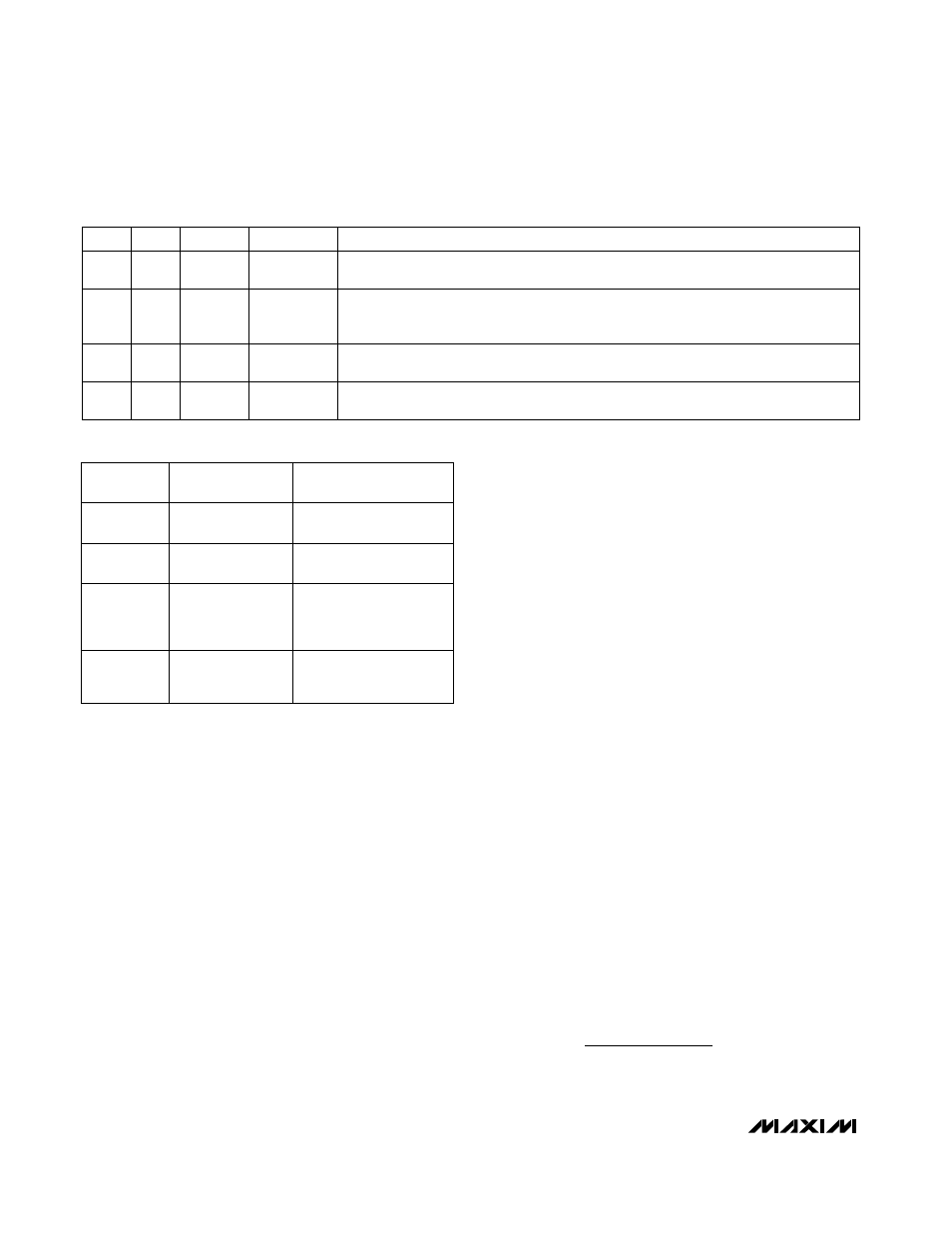
Table 3. Operating Mode Truth Table
Normal operation with automatic PWM/PFM switchover for pulse skipping at light loads.
Best light-load efficiency.
Run
(PFM/PWM)
Switching
GND
1
Low-noise operation with no automatic switchover. Fixed-frequency PWM action is
forced regardless of load. Inductor current reverses at light load levels. Low noise,
high I
Q
.
Run (PWM),
Low Noise
Switching
V
CC
1
Fault latch has been set by overvoltage protection, output UVLO, or thermal shutdown.
Device will remain in FAULT mode until V
CC
power is cycled or SHDN is toggled.
Fault
High
X
1
Low-power shutdown state. DL is forced to V
DD
if OVP is enabled and to GND if OVP is
disabled. I
CC
< 1µA typ.
Shutdown
High or
Low
X
0
COMMENTS
MODE
DL
SKIP
SHDN
Good operating point for
compound buck designs
or desktop circuits.
+5V input
600
TON = GND
450
TON = REF
3-cell Li+ notebook
Useful in 3-cell systems
for lighter loads than the
CPU core or where size is
key.
Considered mainstream
by current standards.
4-cell Li+ notebook
300
TON = Float
200
TON = V
CC
4-cell Li+ notebook
Use for absolute best
efficiency.
COMMENTS
TYPICAL
APPLICATION
FREQUENCY
(kHz)
Table 4. Frequency Selection Guidelines