Max1844 – Rainbow Electronics MAX1844 User Manual
Page 14
MAX1844
Current-Limit Circuit (ILIM)
The current-limit circuit employs a unique “valley” cur-
rent-sensing algorithm (Figure 4). If the magnitude of the
current-sense voltage at CS is above the current-limit
threshold, the PWM is not allowed to initiate a new cycle.
The actual peak current is greater than the current-limit
threshold by an amount equal to the inductor ripple cur-
rent. Therefore, the exact current-limit characteristic and
maximum load capability are a function of the sense
resistance, inductor value, and battery voltage.
There is also a negative current limit that prevents exces-
sive reverse inductor currents when V
OUT
is sinking cur-
rent. The negative current-limit threshold is set to
approximately 120% of the positive current limit and
therefore tracks the positive current limit when ILIM is
adjusted.
The current-limit threshold is adjusted with an external
resistor-divider at ILIM. A 1µA (min) divider current is
recommended. The current-limit threshold adjustment
range is from 25mV to 300mV. In the adjustable mode,
the current-limit threshold voltage is precisely 1/10 the
voltage seen at ILIM. The threshold defaults to 100mV
when ILIM is connected to V
CC
. The logic threshold for
switchover to the 100mV default value is approximately
V
CC
- 1V.
Carefully observe the PC board layout guidelines to
ensure that noise and DC errors do not corrupt the cur-
rent-sense signal seen by CS. Mount or place the IC
close to the low-side MOSFET and sense resistor with
short, direct traces, making a Kelvin sense connection to
the sense resistor.
In Figure 1, the Schottky diode (D1) provides a current
path parallel to the Q2/R
SENSE
current path. Accurate
current sensing demands D1 to be off while Q2 con-
ducts. A void large current-sense voltages that, com-
bined with the voltages across Q2, would allow D1 to
conduct. If very large sense voltages are used, connect
D1 in parallel with Q2.
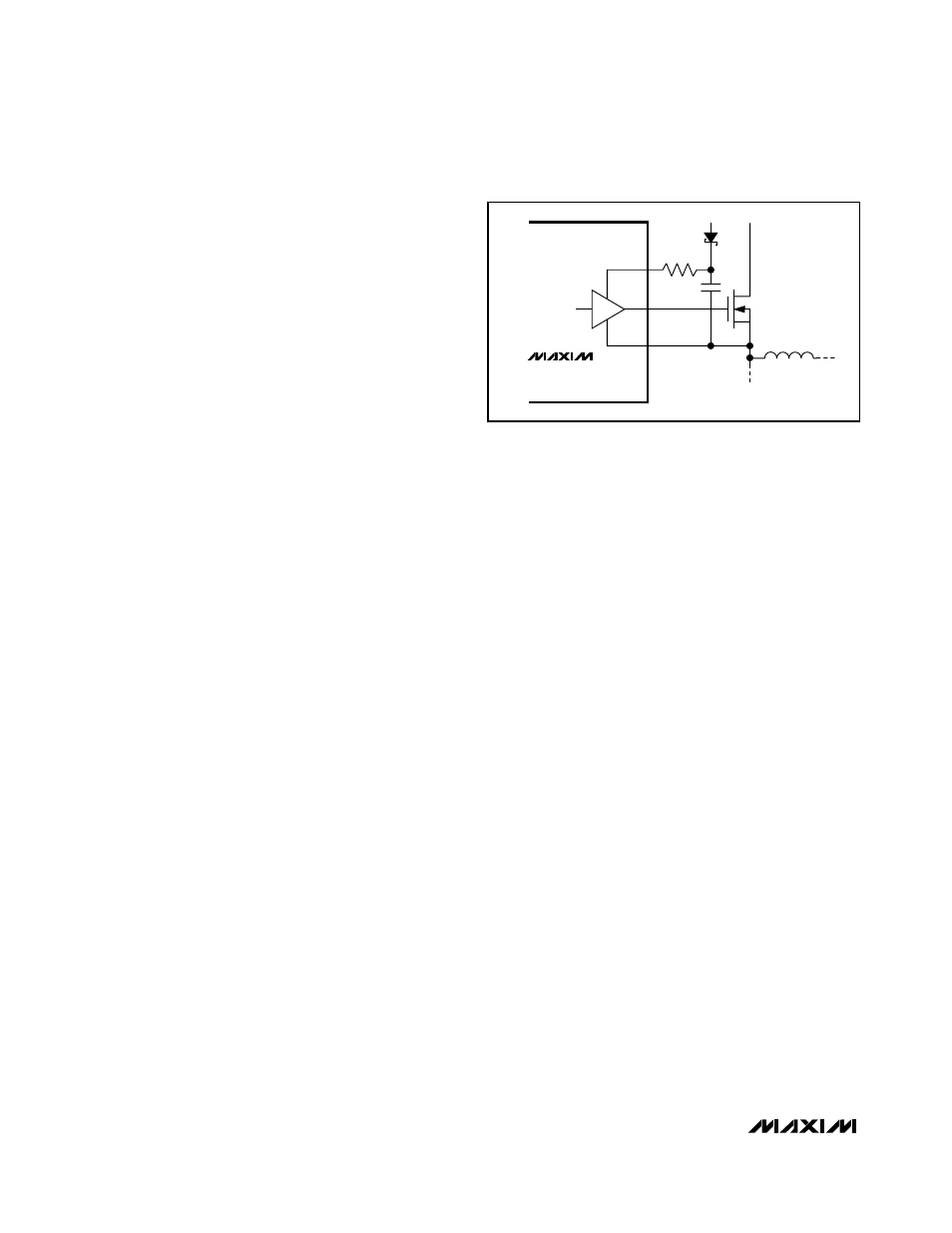
MOSFET Gate Drivers (DH, DL)
The DH and DL drivers are optimized for driving moder-
ate-sized high-side, and larger low-side power
MOSFETs. This is consistent with the low duty factor
seen in the notebook environment, where a large V
BATT
-
V
OUT
differential exists. An adaptive dead-time circuit
monitors the DL output and prevents the high-side FET
from turning on until DL is fully off. There must be a low-
resistance, low-inductance path from the DL driver to the
MOSFET gate for the adaptive dead-time circuit to work
properly; otherwise, the sense circuitry in the MAX1844
will interpret the MOSFET gate as “off” while there is
actually still charge left on the gate. Use very short, wide
traces measuring no more than 20 squares (50 to 100
mils wide if the MOSFET is 1 inch from the MAX1844).
The dead time at the other edge (DH turning off) is deter-
mined by a fixed 35ns (typ) internal delay.
The internal pulldown transistor that drives DL low is
robust, with a 0.5
Ω
(typ) on-resistance. This helps pre-
vent DL from being pulled up during the fast rise-time of
the inductor node, due to capacitive coupling from the
drain to the gate of the low-side synchronous-rectifier
MOSFET. However, for high-current applications, there
are still some combinations of high- and low-side FETs
that will cause excessive gate-drain coupling, which can
lead to efficiency-killing, EMI-producing shoot-through
currents. This is often remedied by adding a resistor in
series with BST, which increases the turn-on time of the
high-side FET without degrading the turn-off time (Figure
5).
POR, UVLO, and Soft-Start
Power-on reset (POR) occurs when V
CC
rises above
approximately 2V, resetting the fault latch and soft-start
counter, and preparing the PWM for operation. Until V
CC
reaches 4.2V, V
CC
undervoltage lockout (UVLO) circuitry
inhibits switching. DL is held low if overvoltage protec-
tion is disabled, and held high if overvoltage protection is
enabled. See the Output Overvoltage Protection section.
When V
CC
rises above 4.2V, an internal digital soft-start
timer begins to ramp up the maximum allowed current
limit. The ramp occurs in five steps: 20%, 40%, 60%,
80%, and 100%; 100% current is available after 1.7ms
±50%.
High-Speed Step-Down Controller with
Accurate Current Limit for Notebook Computers
14
______________________________________________________________________________________
BST
+5V
V
IN
5
Ω
DH
LX
MAX1844
Figure 5. Reducing the Switching-Node Rise Time