Rainbow Electronics MAX1844 User Manual
Page 11
battery supply, the enable signal (SHDN) must be
delayed until the battery voltage is present in order to
ensure startup. The 5V bias supply provides V
CC
and
gate-drive power, so the maximum current drawn is:
I
BIAS
= I
CC
+ f (Q
G1
+ Q
G2
) = 5mA to 30mA (typ)
where I
CC
is 550µA (typ), f is the switching frequency,
and Q
G1
and Q
G2
are the MOSFET data sheet total
gate-charge specification limits at V
GS
= 5V.
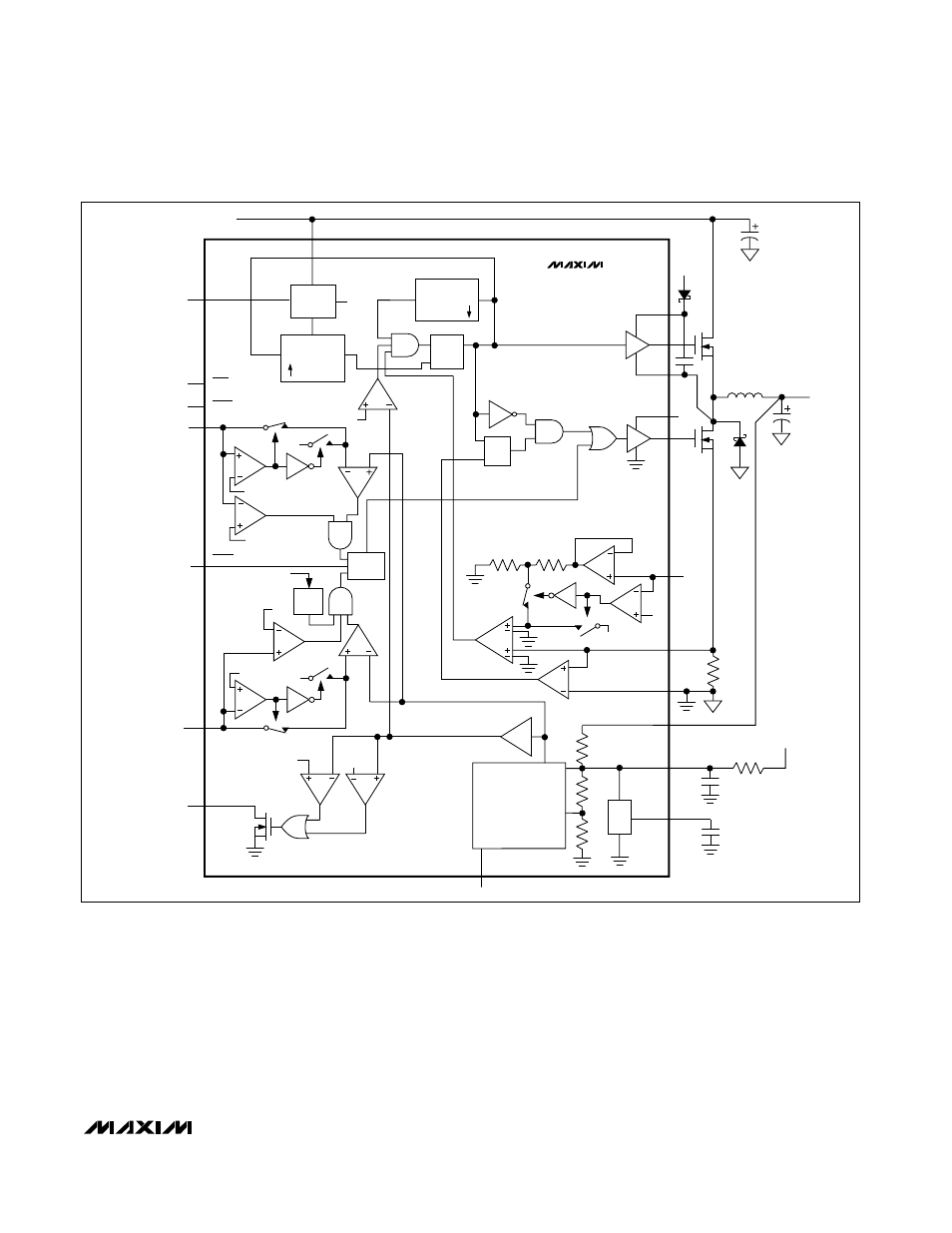
Free-Running, Constant-On-Time PWM
Controller with Input Feed-Forward
The Quick-PWM control architecture is a pseudo-fixed-fre-
quency, constant-on-time on-demand PWM with voltage
feed-forward (Figure 2). This architecture relies on the out-
put filter capacitor’s ESR to act as a current-sense resistor,
so the output ripple voltage provides the PWM ramp sig-
nal. The control algorithm is simple: the high-side switch
on-time is determined solely by a one-shot whose pulse
MAX1844
High-Speed Step-Down Controller with
Accurate Current Limit for Notebook Computers
______________________________________________________________________________________
11
Figure 2. MAX1844 Functional Diagram
REF
-10%
FROM
OUT
REF
FB
ERROR
AMP
TOFF
TON
REF
+10%
FEEDBACK
MUX
(SEE FIGURE 6)
CHIP
SUPPLY
x2
1.0V
R
0.1V
POR
OVP
9R
ILIM
V
CC
- 1V
V
CC
- 1V
V
CC
- 1V
SHDN
PGOOD
ON-TIME
COMPUTE
TON
1-SHOT
1-SHOT
TRIG
IN
2V TO 28V
TRIG
Q
Q
S
R
2V
REF
REF
5V
OUTPUT
DL
CS
GND
V
CC
V
DD
LX
ZERO CROSSING
CURRENT
LIMIT
DH
BST
5V
+5V
Q
SKIP
TON
LATCH
V+
Σ
MAX1844
S
R
Q
0.7V
1.14V
UVP
20ms
TIMER
OVP/UVP
LATCH
0.1V
OUT