Typical operating characteristics (continued), Pin description – Rainbow Electronics MAX1712 User Manual
Page 8
MAX1710/MAX1711/MAX1712
High-Speed, Digitally Adjusted
Step-Down Controllers for Notebook CPUs
8
_______________________________________________________________________________________
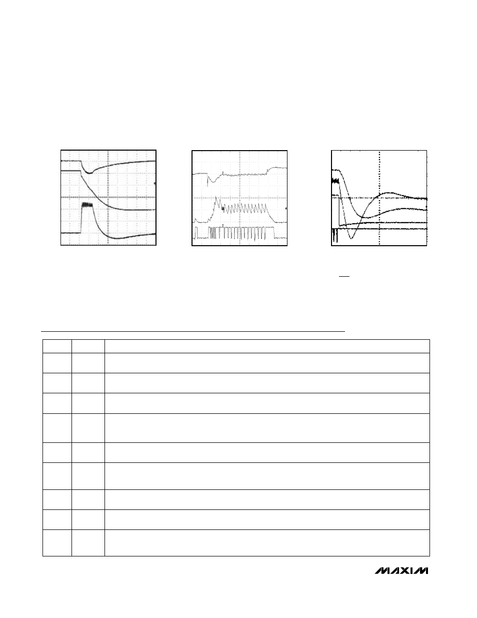
50
µs/div
OUTPUT OVERLOAD WAVEFORM
V
OUT
= 1.6V
A = V
IN
, AC-COUPLED, 2V/div
B = V
OUT
, 0.5V/div
C = INDUCTOR CURRENT, 5A/div
A
B
C
MAX1710-22
5
µs/div
LOAD-TRANSIENT RESPONSE
L = 0.7
µH, V
OUT
= 1.6V, V
IN
= 15V, C
OUT
= 47
µF (x4), f = 550kHz
A = V
OUT
, AC-COUPLED, 100mV/div
B = INDUCTOR CURRENT, 5A/div
C = DL, 5V/div
A
B
C
MAX1710-23
CERAMIC C
OUT
5
µs/div
SHUTDOWN WAVEFORM
V
IN
= 15V, V
0
= 1.6V, I
0
= 7A
A = V
OUT
, 0.5V/div
B = INDUCTOR CURRENT, 5A/div
C = SHDN, 2V/div
D = DL, 5V/div
A
B
C
D
MAX1710-24
_____________________________Typical Operating Characteristics (continued)
(7A CPU supply circuit of Figure 1, T
A
= +25°C, unless otherwise noted.)
Pin Description
NAME
FUNCTION
5
CC
Integrator Capacitor Connection. Connect a 100pF to 1000pF (470pF typical) capacitor to GND to set the
integration time constant.
PIN
4
FBS
Feedback Remote-Sense Input, normally connected to V
OUT
directly at the load. FBS internally connects to
the integrator that fine tunes the DC output voltage. Tie FBS to V
CC
to disable all three integrator amplifiers.
Tie FBS to FB (or disable the integrators) when externally adjusting the output voltage with a resistor-divider.
3
FB
Fast Feedback Input, normally connected to V
OUT
. FB is connected to the bulk output filter capacitors local-
ly at the power supply. An external resistor-divider can optionally set the output voltage.
8
TON
On-Time Selection Control Input. This is a four-level input that sets the K factor to determine DH on-time.
GND = 550kHz, REF = 400kHz, open = 300kHz, V
CC
= 200kHz.
7
V
CC
Analog Supply Voltage Input for PWM Core, 4.5V to 5.5V. Bypass V
CC
to GND with a 0.1µF minimum
capacitor.
6
ILIM
Current-Limit Threshold Adjustment. Connects to an external resistor to GND. The LX-PGND current-limit
threshold defaults to +100mV if ILIM is tied to V
CC
. The current-limit threshold is 1/10 of the voltage forced at
ILIM. In adjustable mode, the threshold is V
TH
= R
LIM ✕
5µA/10.
1
V+
Battery Voltage Sense Connection. V+ is used only for PWM one-shot timing. DH on-time is inversely propor-
tional to V+ input voltage over a range of 2V to 28V.
9
REF
2.0V Reference Output. Bypass REF to GND with a 0.22µF minimum capacitor. REF can source 50µA for
external loads. Loading REF degrades FB accuracy according to the REF load-regulation error
(see Electrical Characteristics).
2
SHDN
Shutdown Control Input, active low. SHDN cannot withstand the battery voltage. In shutdown mode, DL is
forced to V
DD
in order to enforce overvoltage protection, even when powered down (unless OVP is high).