Rainbow Electronics MAX1712 User Manual
Page 11
I
BIAS
= I
CC
+ f
✕
(Q
G1
+ Q
G2
) = 15mA to 30mA (typ)
where I
CC
is 600µA (typ), f is the switching frequency,
and Q
G1
and Q
G2
are the MOSFET data sheet total
gate-charge specification limits at V
GS
= 5V.
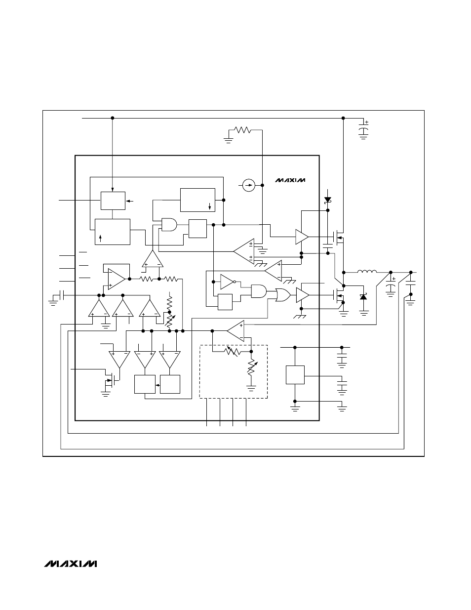
Free-Running, Constant-On-Time PWM
Controller with Input Feed-Forward
The Quick-PWM control architecture is an almost fixed-
frequency, constant-on-time current-mode type with volt-
age feed-forward (Figure 2). This architecture relies on
the filter capacitor’s ESR to act as the current-sense
resistor, so the output ripple voltage provides the PWM
ramp signal. The control algorithm is simple: the high-
side switch on-time is determined solely by a one-shot
whose period is inversely proportional to input voltage
and directly proportional to output voltage. Another one-
shot sets a minimum off-time (400ns typ). The on-time
one-shot is triggered if the error comparator is low, the
MAX1710/MAX1711/MAX1712
High-Speed, Digitally Adjusted
Step-Down Controllers for Notebook CPUs
______________________________________________________________________________________
11
REF
-5%
FROM
D/A
REF
REF
D0
D1
D2
D3
10k
ERROR
AMP
TOFF
TON
REF
+12%
FB
REF
-30%
R-2R
D/A CONVERTER
CHIP SUPPLY
g
m
g
m
g
m
GNDS
CC
SHDN
FBS
PGOOD
OVP/UVLO
LATCH
ON-TIME
COMPUTE
TON
1-SHOT
1-SHOT
TRIG
V
BATT
2V TO 28V
TRIG
Q
Q
S
R
2V
REF
GND
REF
FB
PGND
+5V
OUTPUT
DL
V
CC
V
CC
V
DD
LX
ZERO CROSSING
CURRENT
LIMIT
DH
BST
I
LIM
R
LIM
+5V
5
µA
+5V
Q
S1
Q
S2
TIMER
SKIP
OVP
TON
V+
70k
Σ
MAX1710
S
R
Q
Figure 2. MAX1710 Functional Diagram