Electrical characteristics (continued) – Rainbow Electronics MAX1712 User Manual
Page 3
With respect to unloaded output voltage
MAX1710/MAX1711/MAX1712
High-Speed, Digitally Adjusted
Step-Down Controllers for Notebook CPUs
_______________________________________________________________________________________
3
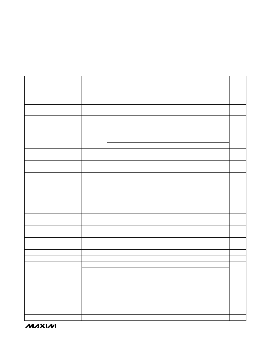
ELECTRICAL CHARACTERISTICS (continued)
(Circuit of Figure 1, V
BATT
= 15V, V
CC
= V
DD
= 5V, SKIP = GND, T
A
= 0°C to +85°C, unless otherwise noted.)
CONDITIONS
UNIT
MIN
TYP
MAX
PARAMETER
LX to PGND
LX to PGND, ILIM tied to V
CC
From SHDN signal going high
mV
40
50
60
Current-Limit Threshold
(Positive Direction, Adjustable)
mV
90
100
110
Current-Limit Threshold
(Positive Direction, Fixed)
ms
10
30
Output Undervoltage Protection
Time
%
65
70
75
Output Undervoltage Protection
Threshold
LX to PGND, T
A
= +25°C
mV
-150
-120
-80
Current-Limit Threshold
(Negative Direction)
R
LIM
= 100k
Ω
R
LIM
= 400k
Ω
170
200
230
Rising edge, hysteresis = 20mV,
PWM disabled below this level
V
4.1
4.4
V
CC
Undervoltage Lockout
Threshold
BST-LX forced to 5V
Ω
5
DH Gate-Driver On-Resistance
DL, high state
Ω
5
DL Gate-Driver On-Resistance
(Pullup)
DL, low state
Ω
0.5
1.7
DL Gate-Driver On-Resistance
(Pulldown)
DH forced to 2.5V, BST-LX forced to 5V
A
1
DH Gate-Driver Source/Sink
Current
DL forced to 2.5V
A
3
DL Gate-Driver Sink Current
DL forced to 2.5V
A
1
DL Gate-Driver Source Current
FB forced 2% above trip threshold
µs
1.5
Overvoltage Fault Propagation
Delay
%
10.5
12.5
14.5
Overvoltage Trip Threshold
FB forced 2% below PGOOD trip threshold, falling edge
µs
1.5
PGOOD Propagation Delay
LX to PGND
mV
3
Current-Limit Threshold
(Zero Crossing)
I
SINK
= 1mA
V
0.4
PGOOD Output Low Voltage
High state, forced to 5.5V
µA
1
PGOOD Leakage Current
Hysteresis = 10°C
°C
150
Thermal Shutdown Threshold
V
2.21
2.25
2.29
0.76
0.8
0.84
With respect to unloaded output voltage (MAX1710)
With respect to unloaded output voltage (MAX1710)
(MAX1711/MAX1712)
V
DL rising
ns
35
Dead Time
DH rising
26
mA
SKIP Input Current Logic
Threshold
To enable no-fault mode, T
A
= +25°C
-1.5
-0.1
%
PGOOD Trip Threshold
Measured at FB with respect to unloaded output voltage,
falling edge, hysteresis = 1%
-8
-5
-3
V
Logic Input High Voltage
D0–D4, SHDN, SKIP, OVP
2.4
V
Logic Input Low Voltage
D0–D4, SHDN, SKIP, OVP
0.8
µA
Logic Input Current
SHDN, SKIP, OVP
-1
1
µA
Logic Input Pullup Current
D0–D4, each forced to GND
3
5
10
(MAX1711/MAX1712)