High-power, dynamically adjustable cpu application – Rainbow Electronics MAX1712 User Manual
Page 23
MAX1710/MAX1711/MAX1712
High-Speed, Digitally Adjusted
Step-Down Controllers for Notebook CPUs
______________________________________________________________________________________
23
DAC code from the transitory value. Use 100ns maxi-
mum rise and fall times.
Selecting the output capacitors in dynamically adjusted
V
CORE
applications can be tricky due to trade-offs
between capacitor capacity and ESR. In other words, if
the capacitor has sufficiently low ESR to meet the load-
transient response specification, its large capacity may
cause excessive input surge currents. On the other
hand, a purely ceramic capacitor may not have enough
capacity to prevent overvoltage during the transition from
full- to no-load condition (see the overshoot equation
under Output Capacitor Selection). It may be necessary
to mix capacitor types or use specialized capacitors
such as those shown in Figure 7 in order to achieve the
required ESR while staying within the min/max capaci-
tance value window.
If the minimum load is very light, it may be necessary to
assert forced PWM mode (via SKIP) during the transition
period to guarantee some output sink current capability.
Otherwise, the output voltage won’t ramp downwards
until pulled down by external load current.
Using forced PWM mode repeatedly to ensure sink cur-
rent capability can have side effects, however. The ener-
gy taken from the output by the synchronous rectifier
isn’t lost, but is instead returned to the input. If the fre-
quency of the high-to-low output voltage transition is high
enough, efficiency will be degraded by the resistive “fric-
tion” losses associated with shuttling energy between
input and output capacitors. Also, if the output is being
overdriven by an external source (such as an external
docking-station power supply), forced PWM mode may
cause the battery voltage to become pumped up, possi-
bly overvoltaging the battery.
High-Power, Dynamically
Adjustable CPU Application
The MAX1711/MAX1712 V
CORE
regulator of Figure 10 is
designed to have its output voltage switched between
1.3V and 1.45V in less than 100µs, while causing a mini-
mum level of input surge current. To this end, the output
capacitors were selected for having the correct value to
a) support the needed ESR, b) prevent excess load-
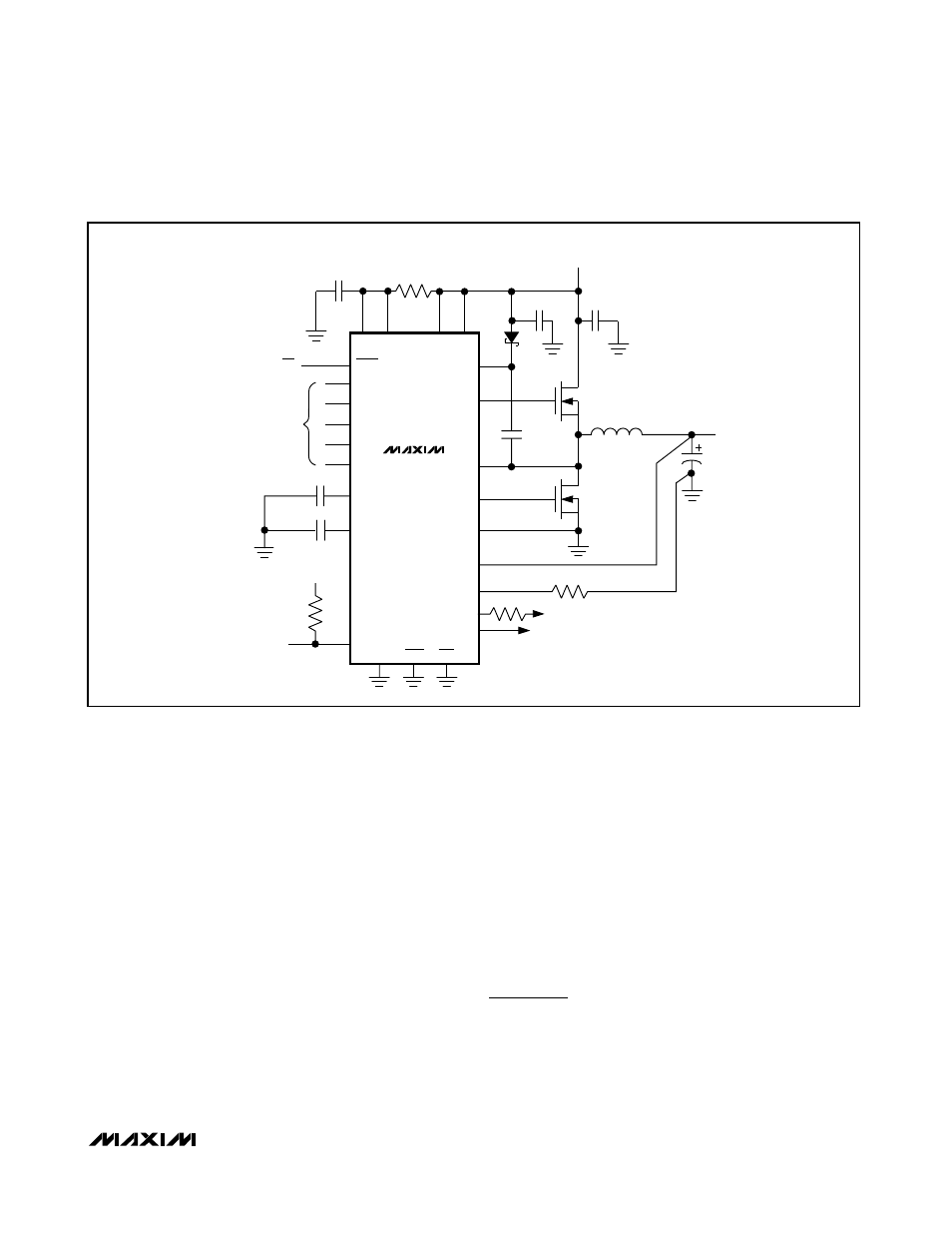
I
LIM
V
CC
V
IN
4.5V TO 5.5V
TO REMOTE
LOAD
L1
0.5
µH
V
OUT
1.6V AT 7A
SHDN
1
µF
0.1
µF
0.22
µF
470pF
C2
3 x 470
µF
KEMET
T510
IRF7805
IRF7805
1
µF
20
Ω
C1
4 x 10
µF/25V
D0
D1
D2
D/A
INPUTS
ON/OFF
DL
LX
BST
DH
PGND
FB
1k
1k
GND
GNDS
FBS
V
DD
V
CC
V+
MAX1710
MAX1711
MAX1712
D4**
D3
REF
CC
TON
SKIP
OVP*
100k
PGOOD
*MAX1710 ONLY
**MAX1711 ONLY
Figure 9. 5V-Powered, 7A CPU Buck Regulator