Pin description – Rainbow Electronics MAX1715 User Manual
Page 8
170
MAX1715
Ultra-High Efficiency, Dual Step-Down
Controller for Notebook Computers
8
_______________________________________________________________________________________
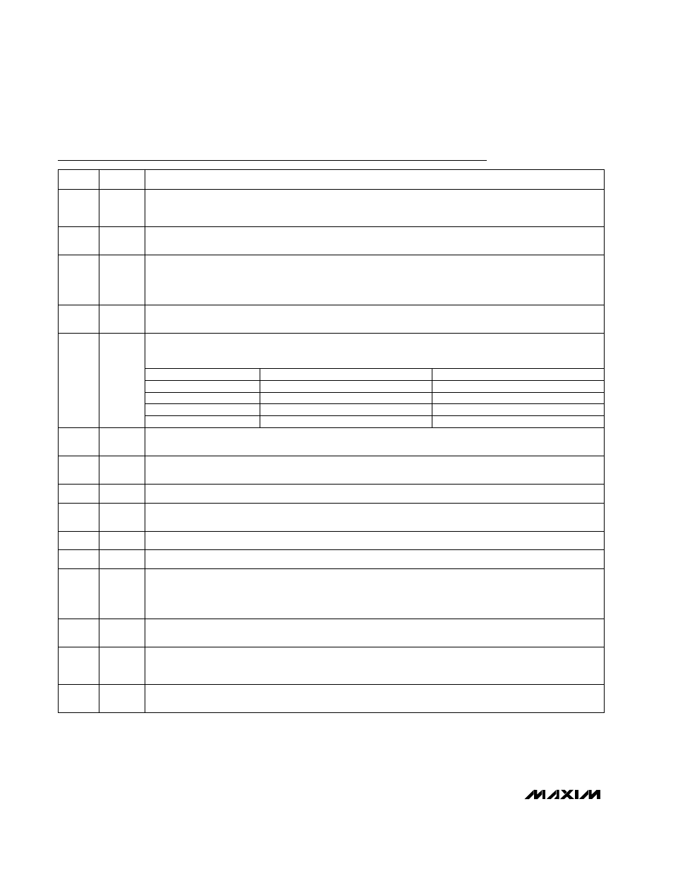
Pin Description
OUT1 ON/OFF Control Input. Drive to AGND to turn OUT1 off. Drive to V
CC
to turn OUT1 on.
ON1
10
Feedback Input for OUT1. Connect to AGND for 1.8V fixed output or to V
CC
for 3.3V fixed output, or connect
to a resistor-divider from OUT1 for an adjustable output.
FB1
2
+2.0V Reference Voltage Connection. Bypass to AGND with 0.22µF (min) capacitor. Can supply 50µA for
external loads.
REF
9
Output Voltage Connection for the OUT1 PWM. Connect directly to the junction of the external inductor and
output filter capacitors. OUT1 senses the output voltage to determine the on-time and also serves as the
feedback input in fixed-output modes.
OUT1
1
Pulse-Skipping Control Input. Connect to V
CC
for low-noise forced-PWM mode. Connect to AGND to enable
pulse-skipping operation.
SKIP
6
Power-Good Open-Drain Output. PGOOD is low when either FB_ input is more than 5.5% below the normal
regulation point (typ).
PGOOD
7
Analog Ground
AGND
8
Current-Limit Threshold Adjustment for OUT1. The LX1-PGND current-limit threshold defaults to +100mV if
ILIM1 is connected to V
CC
. Or, connect an external resistor to AGND to adjust the limit. A precision 5µA pull-up
current through R
EXT
sets the threshold from 50mV to 200mV. The voltage on the pin is 10 times the current-
limit voltage. Choose R
EXT
equal to 2k
Ω per mV of current-limit threshold (100kΩ to 400kΩ).
ILIM1
3
Battery Voltage Sense Connection. Connect to the input power source. V+ is used only to set the PWM one-
shot timing.
V+
4
PIN
On-Time Selection Control Input. This is a four-level input used to determine DH_ on-time. The TON table
below is for V
IN
= 24V, V
OUT1
= 1.8V, V
OUT2
= 2.5V condition.
TON
5
FUNCTION
NAME
OUT2 ON/OFF Control Input. Drive to AGND to turn OUT2 off. Drive to V
CC
to turn OUT2 on.
ON2
11
Current-Limit Threshold Adjustment for OUT2. The LX2-PGND current-limit threshold defaults to +100mV if
ILIM2 is connected to V
CC
. Or, connect an external resistor to AGND to adjust the limit. A precision 5µA pull-up
current through R
EXT
sets the threshold from 50mV to 200mV. The voltage on the pin is 10 times the current-
limit voltage. Choose R
EXT
equal to 2k
Ω per mV of current-limit threshold (100kΩ to 400kΩ).
ILIM2
12
Feedback Input for OUT2. Connect to AGND for 2.5V fixed output, or connect to a resistor-divider from
OUT2 for an adjustable output.
FB2
13
Output Voltage Connection for the OUT2 PWM. Connect directly to the junction of the external inductor and
output filter capacitors. OUT2 senses the output voltage to determine the on-time and also serves as the
feedback input in fixed-output mode.
OUT2
14
No Connection. These pins are not connected to any internal circuitry. Connect the N.C. pins to the ground
plane to enhance thermal conductivity.
N.C.
15, 23,
28
AGND
TON
Open
V
CC
REF
235
345
485
620
Frequency (OUT1) (kHz)
Frequency (OUT2) (kHz)
460
355
255
170