Absolute maximum ratings, Electrical characteristics – Rainbow Electronics MAX1715 User Manual
Page 2
MAX1715
Ultra-High Efficiency, Dual Step-Down
Controller for Notebook Computers
2
_______________________________________________________________________________________
ABSOLUTE MAXIMUM RATINGS
Stresses beyond those listed under “Absolute Maximum Ratings” may cause permanent damage to the device. These are stress ratings only, and functional
operation of the device at these or any other conditions beyond those indicated in the operational sections of the specifications is not implied. Exposure to
absolute maximum rating conditions for extended periods may affect device reliability.
V+ to AGND..............................................................-0.3 to +30V
V
DD
, V
CC
to AGND ..................................................-0.3V to +6V
PGND to AGND or V
CC
to V
DD
...........................................±0.3V
PGOOD, OUT_ to AGND..........................................-0.3V to +6V
ILIM_, FB_, REF, SKIP, TON,
ON_ to AGND ...........................................-0.3V to (V
DD
+ 0.3V)
DL_ to PGND ..............................................-0.3V to (V
DD
+ 0.3V)
BST_ to AGND........................................................-0.3V to +36V
DH1 to LX1 ...............................................-0.3V to (BST1 + 0.3V)
DH2 to LX2 ...............................................-0.3V to (BST2 + 0.3V)
LX1 to BST1..............................................................-6V to +0.3V
LX2 to BST2..............................................................-6V to +0.3V
REF Short Circuit to AGND.........................................Continuous
Continuous Power Dissipation (T
A
= +70°C)
28-Pin QSOP (derate 8.0mW/°C above +70°C).....640mW/°C
Operating Temperature Range ..........................-40°C to +85°C
Junction Temperature ......................................................+150°C
Storage Temperature Range ............................-65°C to +150°C
Lead Temperature (soldering, 10s) .................................+300°C
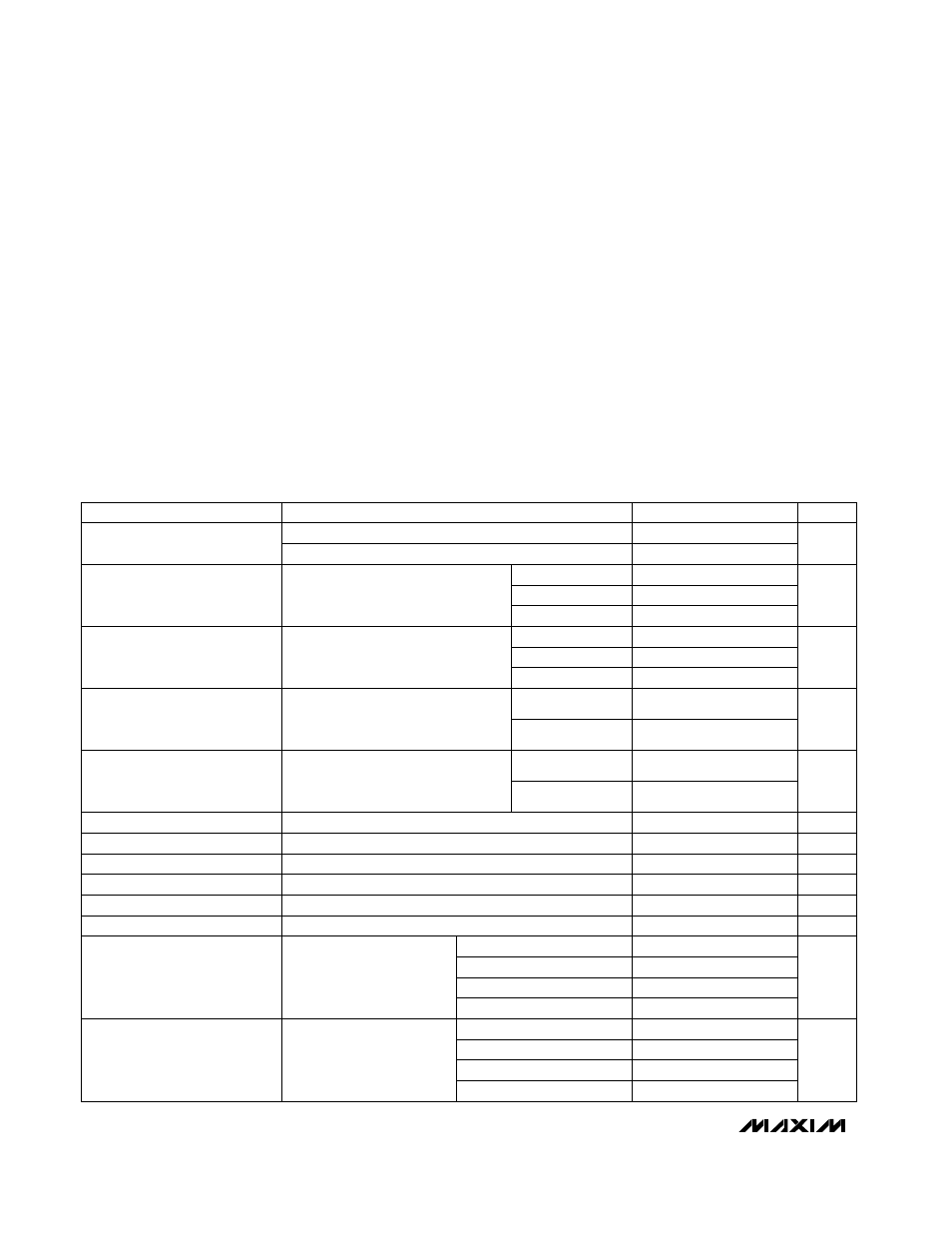
ELECTRICAL CHARACTERISTICS
(Circuit of Figure 1, 4A components from Table 1, V
CC =
V
DD
= +5V, SKIP = AGND, V+ = 15V, T
A
= 0°C to +85°C, unless otherwise
noted.) (Note 1)
I
LOAD
= 0 to 4A, each output
%
0.4
FB2 = GND
Battery voltage, V+
Input Voltage Range
V+ = 24V, OUT2 = 2V
Load Regulation Error
V
CC
= 4.5V to 5.5V, V+ = 4.5V to 28V
V+ = 24V, OUT1 = 2V
Adjustable mode, each output
Output 2 Error Comparator
Threshold (DC Output Voltage
Accuracy) (Note 2)
TON = GND
FB_ Input Bias Current
TON = GND
TON = open
V
OUT
_ = AGND
210
247
280
CONDITIONS
V
TON = REF
142
173
205
ms
TON = V
DD
OUT_ Input Resistance
µA
Soft-Start Ramp Time
Ω
FB_ = AGND
Rising edge of ON_ to full current limit
2.475
2.5
2.525
V+ = 2V to 28V,
SKIP = V
CC
, T
A
= +25°C
I
LOAD
= 0 to 4A
V+ = 2V to 28V,
SKIP = V
CC
, T
A
= +25°C
I
LOAD
= 0 to 4A
ns
154
182
215
V
On-Time (PWM2)
ns
112
136
160
0.99
1.00
1.01
On-Time (PWM1)
V
1.7
0.99
1.00
1.01
300
353
407
1.782
1.8
1.818
-0.1
0.1
TON = open
292
336
380
TON = REF
75k
3.267
3.3
3.333
FB1 = V
CC
FB1 = AGND
FB1 = OUT1
2
28
FB2 = OUT2
V
1
5.5
Output Voltage Range
%
0.2
198
234
270
Line Regulation Error
TON = V
DD
420
484
550
UNITS
MIN
TYP
MAX
PARAMETER
Output 1 Error Comparator
Threshold (DC Output Voltage
Accuracy) (Note 2)
4.5
5.5
V
DD,
V
CC
Output 1 Error Comparator
Threshold (DC Output Voltage
Accuracy) (Note 2)
V+ = 2V to 28V,
SKIP = V
CC
, T
A
= 0°C to +85°C
I
LOAD
= 0 to 4A
V
0.985
1.00
1.105
1.773
1.8
1.827
3.250
3.3
3.350
FB1 = V
CC
FB1 = AGND
FB1 = OUT1
FB2 = GND
Output 2 Error Comparator
Threshold (DC Output Voltage
Accuracy) (Note 2)
2.463
2.5
2.538
V+ = 2V to 28V,
SKIP = V
CC
, T
A
= 0°C to +85°C
I
LOAD
= 0 to 4A
V
0.985
1.00
1.105
FB2 = OUT2