Table 3. operating mode truth table – Rainbow Electronics MAX1715 User Manual
Page 13
MAX1715
Ultra-High Efficiency, Dual Step-Down
Controller for Notebook Computers
______________________________________________________________________________________
13
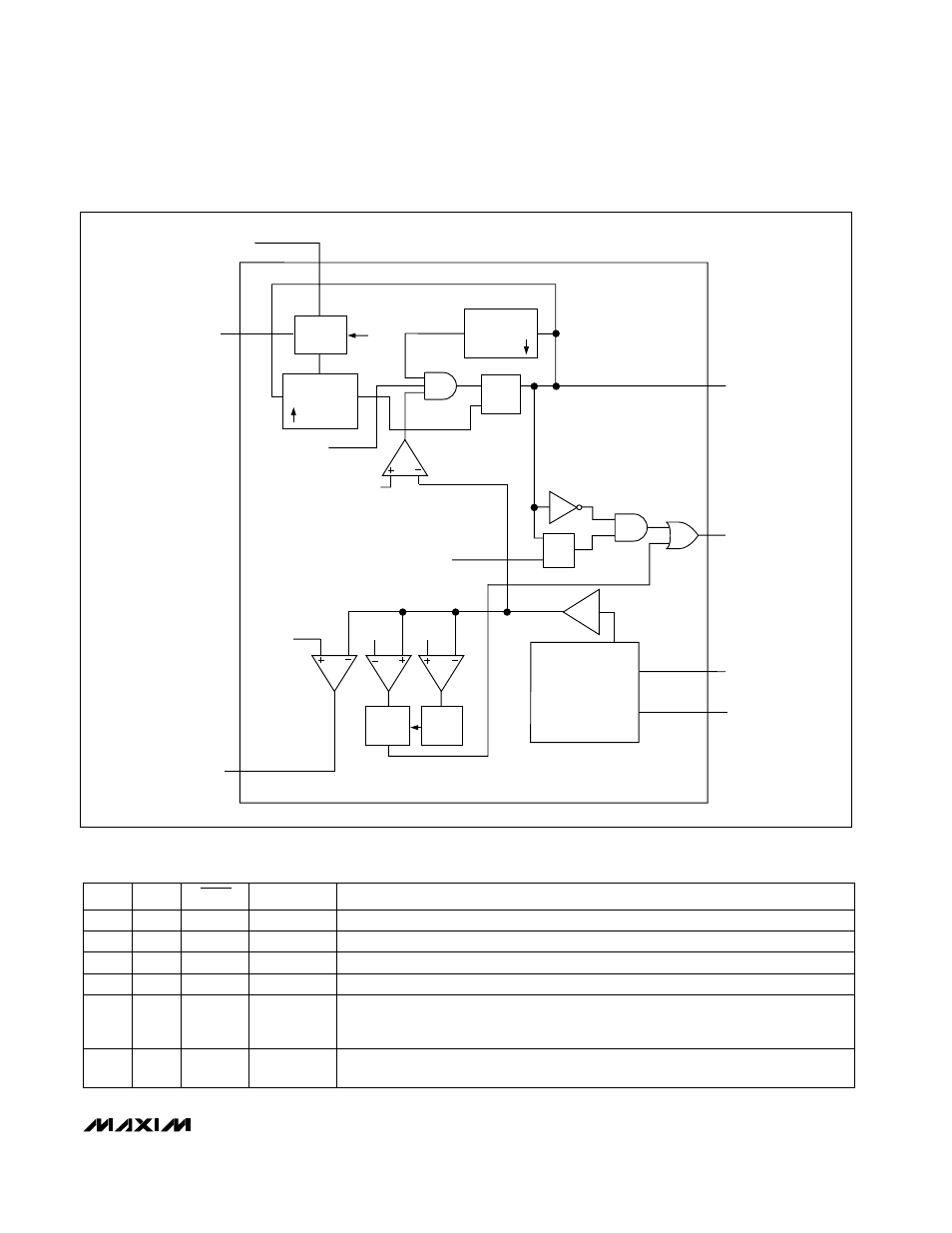
REF
-6%
FROM
OUT
REF
FROM ZERO-CROSSING COMPARATOR
ERROR
AMP
TOFF
TON
REF
+12%
REF
-30%
FEEDBACK
MUX
(SEE FIGURE 9)
x2
OVP/UVLO
LATCH
TO DL DRIVER
TO DH DRIVER
ON-TIME
COMPUTE
TON
1-SHOT
FROM ILIM
COMPARATOR
1-SHOT
TRIG
IN
2V TO 28V
TRIG
Q
Q
S
R
FB_
OUT_
Q
S1
Q
S2
TIMER
TON
V+
S
R
Q
TO PGOOD
OR GATE
Figure 3. PWM Controller (one side only)
X = Don’t care
ON1
ON2
SKIP
MODE
COMMENTS
0
0
X
SHUTDOWN
Low-power shutdown state. DL = V
DD
. Clears fault latches.
0
1
X
OUT1 Disable Disable OUT1. DL1 = V
DD
. Clears OUT1 fault latches.
1
0
X
OUT2 Disable Disable OUT2. DL2 = V
DD
. Clears OUT2 fault latches.
X
X
<-0.3V
No Fault
Disables the output overvoltage and undervoltage fault circuitry.
1
1
V
DD
RUN (PWM)
Low Noise
Low-Noise operation with no automatic PWM/PFM switchover. Fixed-frequency PWM
action is forced regardless of load. Inductor current reverses at light load levels. I
DD
draw <1.5mA (typ) plus gate-drive current.
Table 3. Operating Mode Truth Table
1
1
AGND
RUN
(PFM/PWM)
Normal operation with automatic PWM/PFM switchover for pulse-skipping at light loads.
I
DD
<1.5mA (typ) plus gate drive current.