Rainbow Electronics MAX1715 User Manual
Page 21
MAX1715
Ultra-High Efficiency, Dual Step-Down
Controller for Notebook Computers
______________________________________________________________________________________
21
when going abruptly from full-load to no-load condi-
tions, unless there are some bulk tantalum or electrolyt-
ic capacitors in parallel to absorb the stored energy in
the inductor. In some cases, there may be no room for
electrolytics, creating a need for a DC-DC design that
uses nothing but ceramics.
The all-ceramic-capacitor application of Figure 8
replaces the standard tantalum output capacitors with
ceramics. This design relies on having a minimum of
5m
Ω parasitic PC board trace resistance in series with
the capacitor to reduce the ESR zero frequency. This
small amount of resistance is easily obtained by locat-
ing the MAX1714A circuit 2 or 3 inches away from the
CPU, and placing all the ceramic capacitors close to
the CPU. Resistance values higher than 5m
Ω just
improve the stability (which can be observed by exam-
ining the load-transient response characteristic as
shown in the Typical Operating Characteristics). Avoid
adding excess PC board trace resistance, as there’s an
efficiency penalty; 5m
Ω is sufficient for a 7A circuit:
Output overshoot (
∆V) determines the minimum output
capacitance requirement. In this example, the switch-
ing frequency has been increased to 600kHz and the
inductor value has been reduced to 0.5µH (compared
to 300kHz and 2µH for the standard 8A circuit) to mini-
mize the energy transferred from inductor to capacitor
during load-step recovery. The overshoot must be cal-
culated to avoid tripping the OVP latch. The efficiency
penalty for operating at 540kHz is about 2% to 3%,
depending on the input voltage.
An optional 1
Ω resistor is placed in series with OUT.
This resistor attenuates high-frequency noise in some
bands, which causes double pulsing.
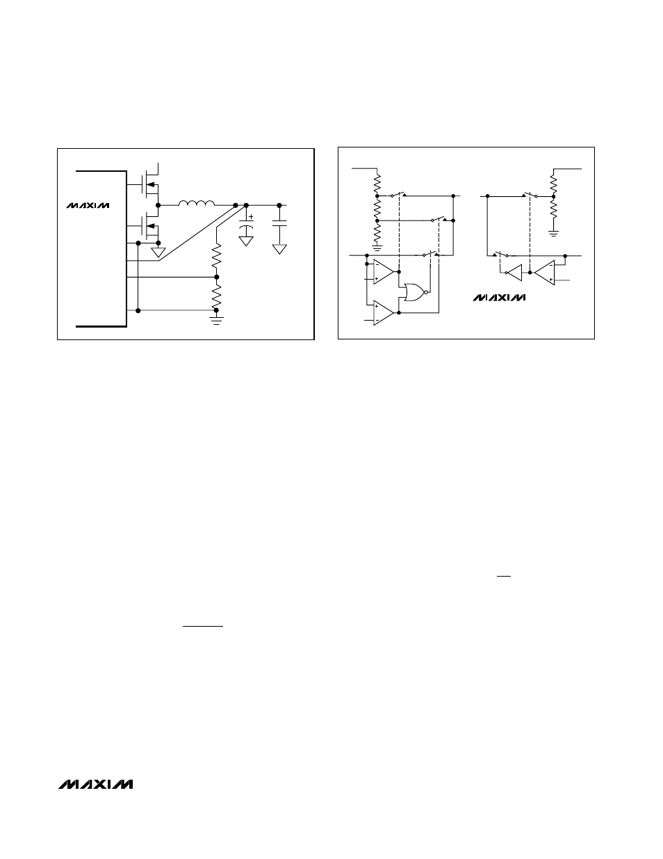
Fixed Output Voltages
The MAX1715’s Dual Mode™ operation allows the
selection of common voltages without requiring external
components (Figure 9). Connect FB to AGND for a
fixed +2.5V output or to V
CC
for a +3.3V output, or con-
nect FB directly to OUT for a fixed +1.0V output.
Setting V
OUT
with a Resistor-Divider
The output voltage can be adjusted with a resistor-
divider if desired (Figure 8). The equation for adjusting
the output voltage is:
where V
FB
is 1.0V and R2 is about 10k
Ω.
Two-Stage (5V-Powered) Notebook
CPU Buck Regulator
The most efficient and overall cost-effective solution for
stepping down a high-voltage battery to a very low out-
put voltage is to use a single-stage buck regulator
that’s powered directly from the battery. However, there
may be situations where the battery bus can’t be routed
near the CPU, or where space constraints dictate the
smallest possible local DC-DC converter. In such
cases, the 5V-powered circuit of Figure 10 may be
appropriate. The reduced input voltage allows a higher
V
V
1
R1
R2
OUT FB
=
+
R
1
2FC
ESR
OUT
≥
MAX1715
TO ERROR
AMP1
TO ERROR
AMP2
OUT2
FB2
0.2V
0.2V
2V
FB1
FIXED
2.5V
FIXED
1.8V
FIXED
3.3V
OUT1
Figure 9. Feedback Mux
DL
AGND
OUT
PGND
DH
1/2
FB
V
BATT
V
OUT
R1
R2
MAX1715
Figure 8. Setting V
OUT
with a Resistor-Divider
Dual Mode is a trademark of Maxim Integrated Products.