Table 5. full scale and zero scale – Rainbow Electronics MAX1083 User Manual
Page 20
MAX1082/MAX1083
300ksps/400ksps, Single-Supply, 4-Channel,
Serial 10-Bit ADCs with Internal Reference
20
______________________________________________________________________________________
UNIPOLAR MODE
BIPOLAR MODE
Full Scale
Zero Scale
Positive
Zero
Negative
Full Scale
Scale
Full Scale
V
REF
+ V
COM
V
COM
V
REF
/ 2
V
COM
-V
REF
/ 2
+ V
COM
+ V
COM
Table 5. Full Scale and Zero Scale
Aperture Jitter
Aperture jitter (t
AJ
) is the sample-to-sample variation in
the time between the samples.
Aperture Delay
Aperture delay (t
AD
) is the time defined between the
rising edge of the sampling clock and the instant when
an actual sample is taken.
Signal-to-Noise Ratio (SNR)
For a waveform perfectly reconstructed from digital
samples, the SNR is the ratio of the full-scale analog
input (RMS value) to the RMS quantization error (resid-
ual error). The ideal, theoretical minimum analog-to-dig-
ital noise is caused only by quantization error and
results directly from the ADC’s resolution (N bits):
SNR = (6.02 x N + 1.76)dB
In reality, there are other noise sources besides quanti-
zation noise, including thermal noise, reference noise,
clock jitter, etc. Therefore, SNR is calculated by taking
the ratio of the RMS signal to the RMS noise, which
includes all spectral components minus the fundamen-
tal, the first five harmonics, and the DC offset.
Signal-to-Noise Plus Distortion (SINAD)
SINAD is the ratio of the fundamental input frequency’s
RMS amplitude to RMS equivalent of all other ADC out-
put signals:
SINAD (dB) = 20 x log (Signal
RMS
/ Noise
RMS
)
Effective Number of Bits (ENOB)
ENOB indicates the global accuracy of an ADC at a
specific input frequency and sampling rate. An ideal
ADC’s error consists only of quantization noise. With an
input range equal to the ADC’s full-scale range, calcu-
late ENOB as follows:
ENOB = (SINAD - 1.76) / 6.02
Total Harmonic Distortion (THD)
THD is the ratio of the RMS sum of the input signal’s
first five harmonics to the fundamental itself. This is
expressed as:
where V
1
is the fundamental amplitude, and V
2
through
V5 are the amplitudes of the 2nd- through 5th-order
harmonics.
Spurious-Free Dynamic Range (SFDR)
SFDR is the ratio of the RMS amplitude of the funda-
mental (maximum signal component) to the RMS value
of the next-largest distortion component.
THD 20 log
V
V
V
V
V
V
2
2
3
2
4
2
4
2
5
2
1
=
×
+
+
+
+
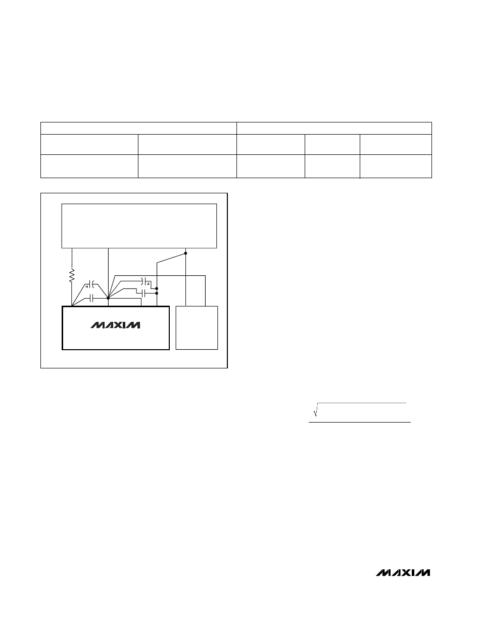
+3V
+3V
SUPPLIES
DGND
+3V
V
DD2
COM
GND
V
DD
DIGITAL
CIRCUITRY
MAX1082
MAX1083
*R = 10
Ω
*OPTIONAL
GND
Figure 15. Power-Supply Grounding Connection