Definitions, Integral nonlinearity, Differential nonlinearity – Rainbow Electronics MAX1083 User Manual
Page 19: Aperture width
MAX1082/MAX1083
300ksps/400ksps, Single-Supply, 4-Channel,
Serial 10-Bit ADCs with Internal Reference
______________________________________________________________________________________
19
CLKR (TMS320 receive clock) as an active-high
input clock. CLKX and CLKR on the TMS320 are
connected to the MAX1082/MAX1083’s SCLK input.
2) The MAX1082/MAX1083’s CS pin is driven low by
the TMS320’s XF_ I/O port to enable data to be
clocked into the MAX1082/MAX1083’s DIN pin.
3) An 8-bit word (1XXXXX11) should be written to the
MAX1082/MAX1083 to initiate a conversion and
place the device into normal operating mode. See
Table 3 to select the proper XXXXX bit values for your
specific application.
4) The MAX1082/MAX1083’s SSTRB output is moni-
tored through the TMS320’s FSR input. A falling
edge on the SSTRB output indicates that the con-
version is in progress and data is ready to be
received from the device.
5) The TMS320 reads in 1 data bit on each of the next
16 rising edges of SCLK. These data bits represent
the 10 + 2-bit conversion result followed by 4 trailing
bits, which should be ignored.
6) Pull CS high to disable the MAX1082/MAX1083 until
the next conversion is initiated.
Definitions
Integral Nonlinearity
Integral nonlinearity (INL) is the deviation of the values
from a straight line on an actual transfer function. This
straight line can be a best-straight-line fit or a line
drawn between the endpoints of the transfer function,
once offset and gain errors have been nullified. The
static linearity parameters for the MAX1082/MAX1083
are measured using the best straight-line fit method.
Differential Nonlinearity
Differential nonlinearity (DNL) is the difference between
an actual step width and the ideal value of 1LSB. A
DNL error specification of less than 1LSB guarantees
no missing codes and a monotonic transfer function.
Aperture Width
Aperture width (t
AW
) is the time the T/H circuit requires
to disconnect the hold capacitor from the input circuit
(for instance, to turn off the sampling bridge, and put
the T/H unit in hold mode).
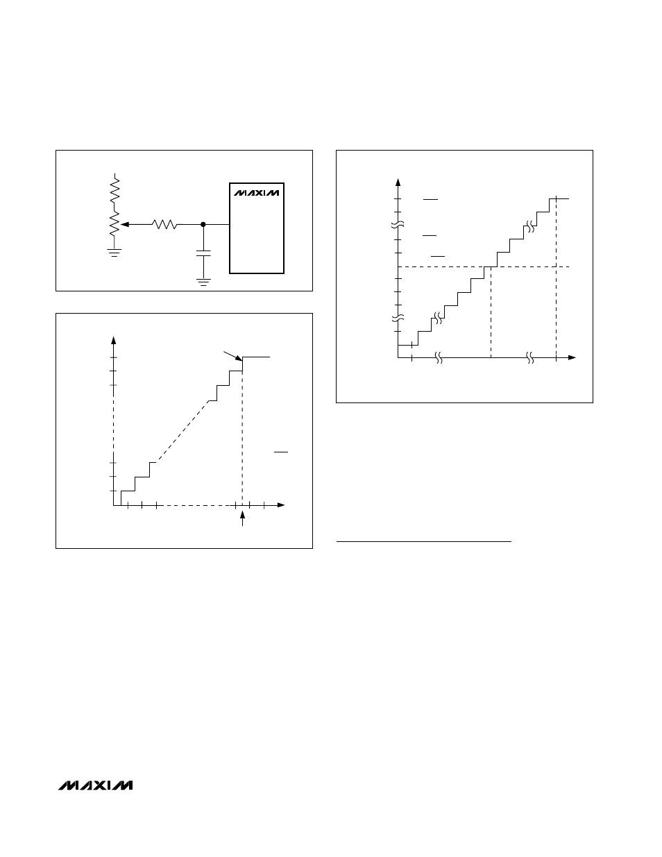
+3.3V
510k
24k
100k
0.047µF
12
REFADJ
MAX1082
MAX1083
Figure 12. MAX1082/MAX1083 Reference-Adjust Circuit
OUTPUT CODE
FULL-SCALE
TRANSITION
11 . . . 111
11 . . . 110
11 . . . 101
00 . . . 011
00 . . . 010
00 . . . 001
00 . . . 000
1
2
3
0
(COM)
FS
FS - 3/2LSB
FS = V
REF
+ V
COM
ZS = V
COM
INPUT VOLTAGE (LSB)
1LSB =
V
REF
1024
Figure 13. Unipolar Transfer Function, Full Scale (FS) = V
REF
+ V
COM
, Zero Scale (ZS) = V
COM
011 . . . 111
011 . . . 110
000 . . . 010
000 . . . 001
000 . . . 000
111 . . . 111
111 . . . 110
111 . . . 101
100 . . . 001
100 . . . 000
- FS
COM*
INPUT VOLTAGE (LSB)
OUTPUT CODE
ZS = V
COM
+FS - 1LSB
*V
COM
V
REF
/ 2
+ V
COM
FS
=
V
REF
2
-FS =
+ V
COM
-V
REF
2
1LSB =
V
REF
1024
≤
Figure 14. Bipolar Transfer Function, Full Scale (FS) =
V
REF
/ 2 + V
COM
, Zero Scale (ZS) = V
COM