Rainbow Electronics MAX1083 User Manual
Page 15
MAX1082/MAX1083
300ksps/400ksps, Single-Supply, 4-Channel,
Serial 10-Bit ADCs with Internal Reference
______________________________________________________________________________________
15
Software Power-Down
Software power-down is activated using bits PD1 and
PD0 of the control byte. When software power-down is
asserted, the ADC completes the conversion in
progress and powers down into the specified low-qui-
escent-current state (2µA, 0.9mA, or 1.3mA).
The first logic 1 on DIN is interpreted as a start bit and
puts the MAX1082/MAX1083 into its full-power mode.
Following the start bit, the data input word or control
byte also determines the next power-down state. For
example, if the DIN word contains PD1 = 0 and PD0 = 1, a
0.9mA power-down resumes after one conversion.
Table 4 details the four power modes with the corre-
sponding supply current and operating sections.
Hardware Power-Down
Pulling SHDN low places the converter in hardware
power-down. Unlike software power-down mode, the
conversion is not completed; it stops coincidentally with
SHDN being brought low. When returning to normal
operation—from SHDN, with an external reference—the
MAX1082/MAX1083 can be considered fully powered
up within 2µs of actively pulling SHDN high. When
using the internal reference, the conversion should be
initiated only when the reference has settled; its recov-
ery time is dependent on the external bypass capaci-
tors and the time between conversions.
Power-Down Sequencing
The MAX1082/MAX1083 auto power-down modes can
save considerable power when operating at less than
maximum sample rates. Figures 9 and 10 show the
average supply current as a function of the sampling
rate. The following sections discuss the various power-
down sequences. Other combinations of clock rates
and power-down modes may attain the lowest power
consumption in other applications.
Using Full Power-Down Mode
Full power-down mode (FULLPD) achieves the lowest
power consumption, up to 1000 conversions per chan-
nel per second. Figure 9a shows the MAX1083’s power
consumption for one- or four-channel conversions utiliz-
ing full power-down mode (PD1 = PD0 = 0), with the
internal reference and conversion controlled at the
maximum clock speed. A 0.01µF bypass capacitor at
REFADJ forms an RC filter with the internal 17k
Ω refer-
ence resistor, with a 170µs time constant. To achieve
full 10-bit accuracy, seven time constants or 1.2ms are
required after power-up if the bypass capacitor is fully
discharged between conversions. Waiting this 1.2ms
duration in fast power-down (FASTPD) or reduced-
power (REDP) mode instead of in full power-up can fur-
ther reduce power consumption. This is achieved by
using the sequence shown in Figure 11a.
Figure 9b shows the MAX1083’s power consumption for
one- or four-channel conversions utilizing FULLPD
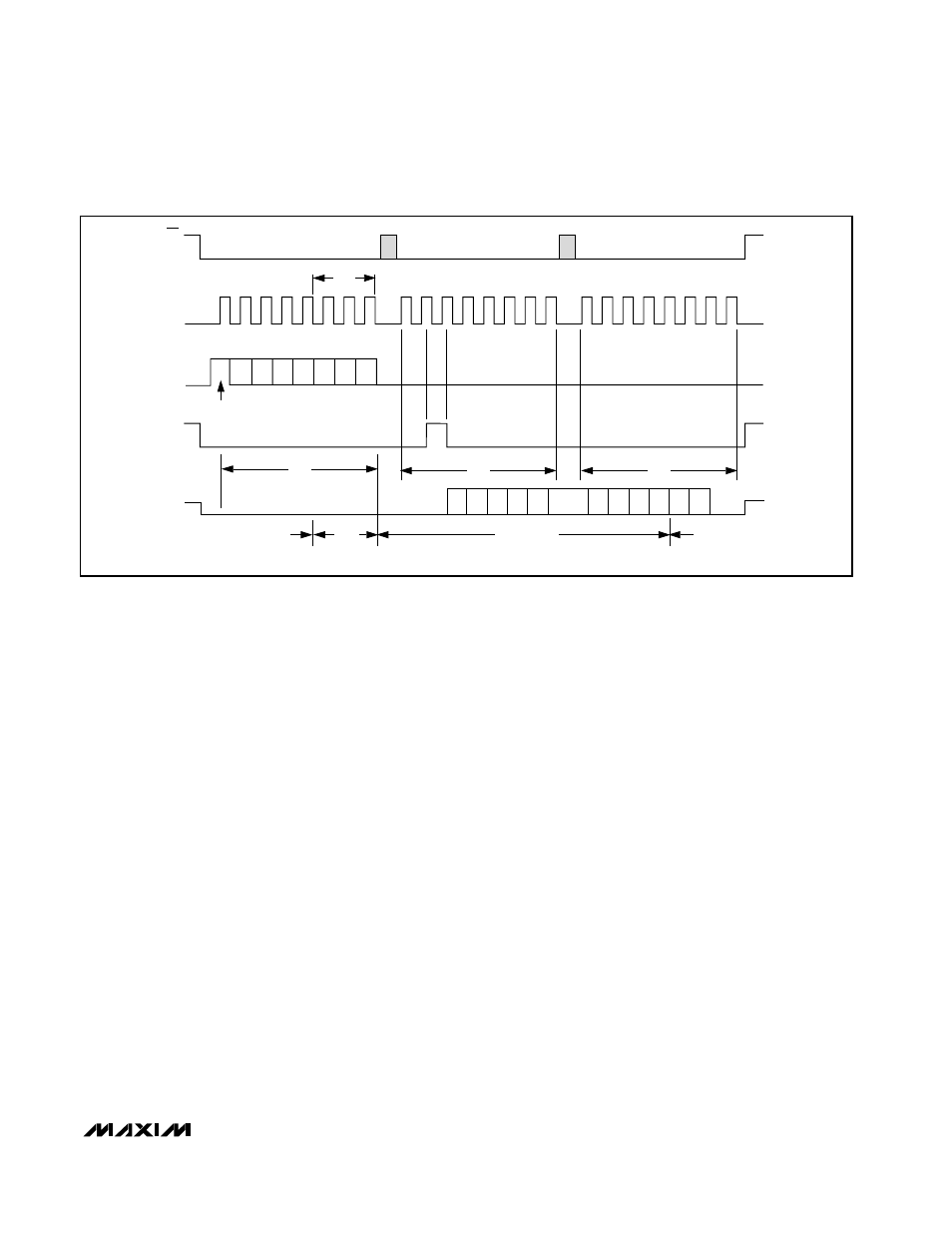
400ns
(CLK = 6.4MHz)
IDLE
CS
SCLK
DIN
SSTRB
DOUT
A/D STATE
t
ACQ
IDLE
CONVERSION
RB3
RB2
RB1
SEL
2
1
START
4
8
9
12
16
20
24
SEL
1
SEL
0
UNI/
BIP
SGL/
DIF
PD2 PD2
B9 B8
B7
B6 B5
B4
B3
B2
B1 B0
S1
S0
Figure 5. Single-Conversion Timing