Max1802 digital camera step-down power supply, Applications information – Rainbow Electronics MAX1802 User Manual
Page 25
MAX1802
Digital Camera Step-Down
Power Supply
______________________________________________________________________________________
25
The frequency (in Hz) of the zero due to the ESR of the
output capacitor is:
and the right-half-plane zero frequency (in Hz) is:
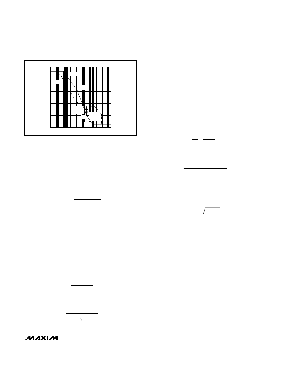
Figure 8 shows the Bode plot of the loop gain of this
control circuit.
To configure the compensation network for a stable
control loop, set the crossover frequency at that of the
zero due to the output capacitor ESR. Use the following
procedure:
1) Determine the frequency of the right-half-plane
zero:
2) Find the DC loop gain:
3) Determine the frequency of the complex pole pair
due to the inductor and output capacitor:
4) Since response is 2nd order (-40dB per decade)
between the complex pole pair and the ESR zero,
determine the desired amplitude at the complex
pole pair to force the crossover frequency equal to
the ESR zero frequency. Thus:
5) Determine the desired compensation pole. Since
the response between the compensation pole and
the complex pole pair is 1st order (-20dB per
decade), the ratio of the frequencies is equal to the
ratio of the amplitudes at those frequencies. Thus:
Solving this equation for C
C
:
6) Determine R
C
for the compensation zero frequency
as equal to the complex pole-pair frequency:
Z
C
= P
O
.
Solving for R
C
:
Applications Information
Using the MAX1801 with the MAX1802
Step-Down Master
The MAX1801 is a slave DC-DC controller that can be
used with the MAX1802 to generate additional output
voltages. The MAX1801 does not generate its own ref-
erence or oscillator. Instead it uses the reference and
oscillator from the MAX1802 step-down master convert-
er controller (Figure 1). MAX1801 controller operation
and design is similar to that of the MAX1802 auxiliary
controllers. For more details, refer to the MAX1801 data
sheet.
Using an Auxiliary Controller in an
SEPIC Configuration
Where the battery voltage may be above or below the
required output voltage, neither a step-up nor a step-
down converter is suitable; instead, use a step-up/step-
down converter. One type of step-up/step-down
R
V
V
C
C
IN
OUT
C
=
LC
OUT
C
V
C
E
V
C
OUT
OUT
IN
=
(
)
Ω
( )
3 2
2
1 2
20
/
/
SR
M
L
P
P
A
O
C
DC
=
( )
A P
O
A P
V
C
O
IN
( )
=
(
)
=
Z
P
L
ESR V
O
O
OUT
OUT
/
2
2
2
2
f
V
O
OUT
=
2
π V
LC
IN
OUT
A
V
VDC
IN
=
2000V
OUT
Z
1-D
2
RHP
=
( )
2
R
L
LOAD
π
Z
1-D
2
RHP
=
( )
2
R
L
LOAD
π
Z
1
2 C
E
O
OUT
=
π
SR
FREQUENCY
A
VDC
PHASE
180
°
90
°
0
°
0
PHASE
GAIN
Z
C
= P
O
Z
0
Z
RHP
PHASE
MARGIN
GAIN
MARGIN
A
VDC
GAIN
(dB)
-10
10
20
30
P
C
40
Figure 8. Continuous-Current, Voltage-Mode, Step-Up
Converter Bode Plot