Max1802 digital camera step-down power supply – Rainbow Electronics MAX1802 User Manual
Page 16
MAX1802
Digital Camera Step-Down
Power Supply
16
______________________________________________________________________________________
Core DC-DC Converter
The MAX1802 core step-down DC-DC converter gener-
ates a 1.25V to 5.5V output voltage from the main con-
troller output. The core converter has the same
low-noise, constant-frequency PWM current-mode
architecture as the main controller. However, it uses an
internal P-channel MOSFET power switch and N-chan-
nel MOSFET synchronous rectifier to maximize efficien-
cy and reduce circuit size and external component
count. The core converter internally monitors the induc-
tor current for current-mode regulation of the output
voltage, as well as overload protection, automatic Idle
Mode switchover, and turning off the synchronous recti-
fier when the inductor current approaches zero. By
switching to Idle Mode at light loads and turning the
synchronous rectifier off at zero current, light-load effi-
ciency is improved. The core converter is inactive until
the main output has started.
The voltage at COMPC is typically clamped to
V
COMPC(MAX)
= 2.14V, thereby limiting the inductor
current. The peak inductor current limit (I
LIM
) and the
maximum average output current (I
OUT(MAX)
) are
determined by the following equations:
where A
VSWC
is the core slope compensation gain
(0.20V/V), R
CSC
is the transresistance of the core cur-
rent-sense amplifier (1V/A), and L is the inductor value.
Note that the current limit increases as the input/output
ratio increases.
Auxiliary DC-DC Controllers
The MAX1802’s three auxiliary controllers operate in a
low-noise, fixed-frequency, PWM mode with output
power limited by the external components. The con-
I
V
V
V
A
V
R
I
I
V
V
V
f
L
LIM
COMPC MAX
REF
OUT
VSWC
IN
CSC
OUT MAX
LIM
OUT
IN
OUT
OSC
=
−
+
=
−
−
(
)
(
)
1
1
2
OSC
COMPM
FBM
ONM
COMPC
FBC
ONC
SOFT-START
V
REF
V
REF
V
REF
SOFT-START
PGND
LXC
VDDC
GND
VL
PGNDM
DLM
LXM
DHM
VDDM
VH
REF
REFERENCE
VH
MAIN
CURRENT-MODE DC-DC
CONTROLLER
VL LDO
CLK
CLK
100ns
ONE-SHOT
CLK
2.4V
CORE
CURRENT MODE
DC-DC
CONTROLLER
CLOCK
GENERATOR
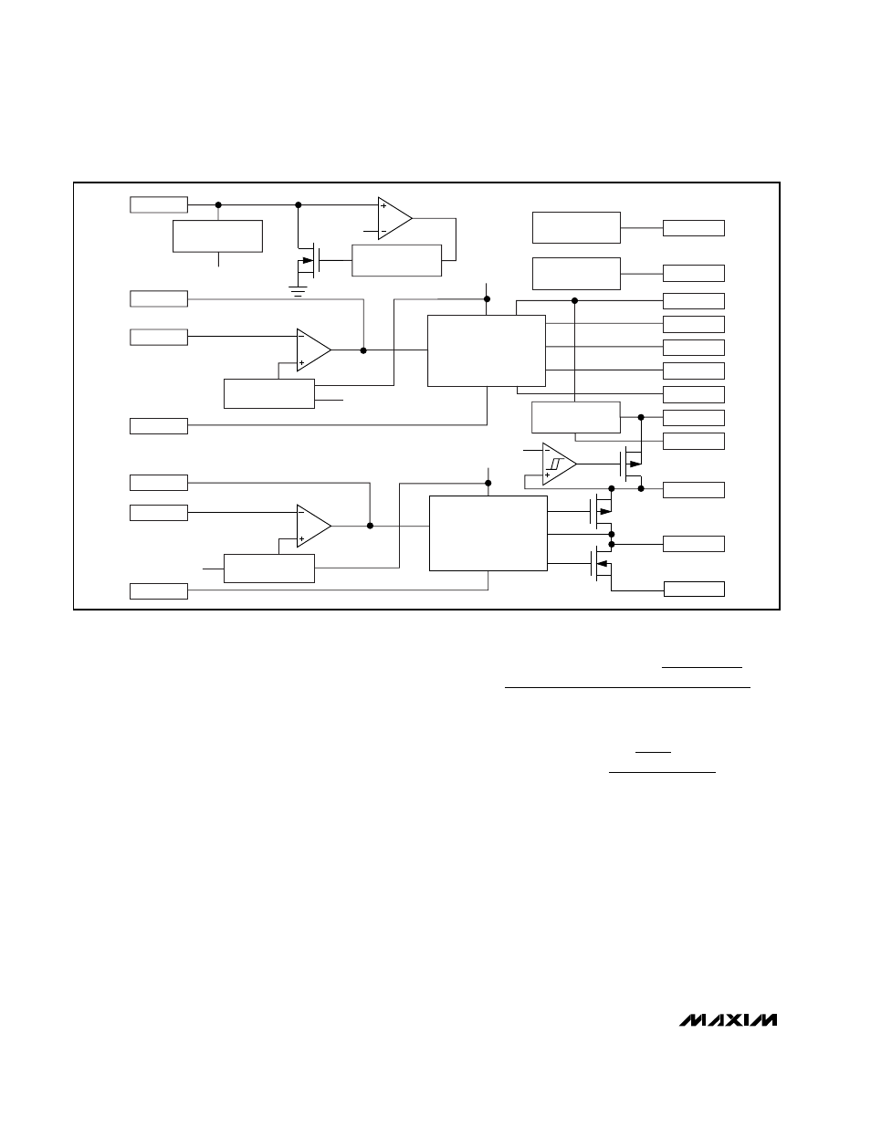
Figure 2. Simplified Block Diagram, Including Main and Core