Max1802 digital camera step-down power supply – Rainbow Electronics MAX1802 User Manual
Page 17
MAX1802
Digital Camera Step-Down
Power Supply
______________________________________________________________________________________
17
trollers regulate their output voltages by modulating the
pulse width of the drive signal for an external N-channel
MOSFET switch. The auxiliary controllers are inactive
until the main output has started.
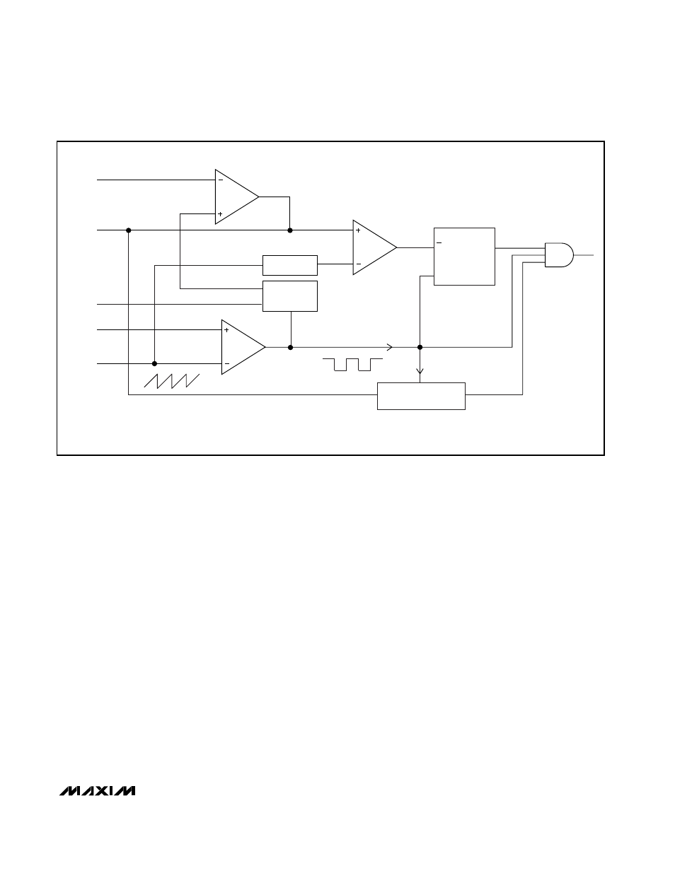
Figure 3 shows a block diagram for a MAX1802 auxil-
iary PWM controller. The sawtooth oscillator signal at
OSC governs the internal timing. At the beginning of
each cycle, DL_ goes high to turn on the external MOS-
FET switch. The MOSFET switch turns off when the
internally level-shifted sawtooth rises above COMP_ or
when the maximum duty cycle is exceeded. The switch
remains off until the beginning of the next cycle. An
internal transconductance amplifier establishes an inte-
grated error voltage at COMP_, thereby increasing the
loop gain for improved regulation accuracy.
Power-Up Sequence
The MAX1802 is in the shutdown state with all circuitry
off when the ONM input is low (<1.3V). When ONM
goes high, an internal linear regulator generates 3V at
the VL output from the VDDM input to power internal
circuitry. As VL rises above the 2.4V undervoltage lock-
out threshold, the internal reference and oscillator
begin to function and the main DC-DC converter
begins soft-start operation. The main DC-DC output
reaches full regulation voltage after 1024 soft-start
oscillator cycles. Once the main DC-DC converter com-
pletes soft-start, the core DC-DC converter and the
auxiliary DC-DC controllers are enabled.
As the voltage at VDDC rises above 2.4V, the internal
linear regulator turns off and an internal 3
Ω switch con-
nects VL directly to VDDC, which is typically connected
to the output of the main DC-DC converter.
The core DC-DC converter and the auxiliary DC-DC
controllers have independent on-off control and soft-
start. The main DC-DC converter shuts down with a low
input at ONM. The core DC-DC converter shuts down
with a low input at ONC. Turn auxiliary DC-DC convert-
er 1 off by driving either ON1 or DCON1 to GND. Turn
off auxiliary controller 2 or 3 by driving DCON2 or
DCON3 to GND.
Reference
The MAX1802 has an internal 1.248V, 1% reference.
Connect a 0.1µF bypass capacitor from REF to GND
within 0.2in (5mm) of the REF pin. REF can source up
to 200µA of external load current, and it is enabled
whenever ONM is high and VL is above the undervolt-
R
Q
DL_
S
CLK
FAULT
PROTECTION
LEVEL
SHIFT
REF
COMP_
FB_
DCON_
OSC
SOFT-
START
Figure 3. Auxiliary Controller Block Diagram