Max1802 digital camera step-down power supply – Rainbow Electronics MAX1802 User Manual
Page 22
MAX1802
Digital Camera Step-Down
Power Supply
22
______________________________________________________________________________________
and the output voltage is I
OUT
R
LOAD
, which is equal to
I
L
R
LOAD
. Thus, the total DC loop gain is:
A
VDC
= R
LOAD
A
VDV
A
VEA
/ (A
VCSM
R
DSP
)
or
A
VDC
= 215 V
REF
R
LOAD
/ (V
OUT
R
DS(ON)
)
Because of the current-mode control, there is a single
pole in the loop response due to the output capacitor.
This pole is at the frequency (in Hz):
P
O
= 1 / (2
π
R
LOAD
C
OUT
)
Note that as the load resistance increases, the pole
moves to a lower frequency. However, the DC loop
gain increases by the same amount since they are both
dependent on R
LOAD
. Thus, the crossover frequency
(frequency at which the loop gain drops to 0dB), which
is the product of the pole and the gain, remains at the
same frequency.
The compensation network creates a pole and zero at
the frequencies (in Hz):
P
C
= G
EA
/ (4000
π
C
C
) = 1 / (4x10⁷
π
C
C
)
and
Z
C
= 1 / (2
π
R
C
C
C
)
and the ESR of the output filter capacitor causes a zero
in the loop response at the frequency (in Hz):
Z
O
= 1 / (2
π
C
OUT
ESR)
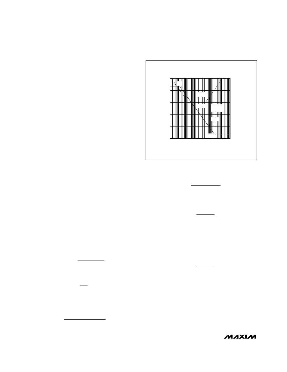
The DC gain and the poles and zeros are shown in the
Bode plot of Figure 6.
To achieve a stable circuit with the Bode plot of Figure
6, use the following procedure:
1) Determine the desired crossover frequency, either
1/3 of the zero due to the output capacitor ESR:
or 1/5 of the switching frequency:
whichever is lower.
2) Determine the pole frequency due to the output
capacitor and the load resistor:
or
3) Determine the compensation resistor required to set
the desired crossover frequency:
or, by simplifying and using the typical V
REF
= 1.25V:
R
C
= 468k
Ω/V V
OUT
C
OUT
R
DSP
f
C
4) Determine the compensation capacitor to set the
proper error-amplifier pole and zero determined from
the above equations:
Core Converter
Compensating the core converter is similar to the com-
pensation of the main converter described above. The
only difference is that the current is measured internal-
ly, and the gain (transresistance) of the current-sense
amplifier is R
CSC
= 1.0V/A. The DC loop gain is:
A
VDC
= 2000 V
REF
R
LOAD
/ V
OUT
C
P
C O
C
1
2 R
=
π
R
M f
A
P
C
VDC O
C
=
Ω
20
P
C
LOAD MAX
OUT
OUT
O
I
2 V
=
(
)
π
P
C
LOAD MIN
OUT
O
1
2 R
=
π
(
)
f
C
=
f
SW
5
f
Z
1
6 C
E
C
O
=
=
/ 3
π
OUT
SR
FREQUENCY
A
VDC
GAIN
(dB)
PHASE
180
°
90
°
0
°
O
PHASE
PHASE
MARGIN
Z
C
= P
O
P
C
Z
0
GAIN
Figure 6. Current-Mode Step-Down Converter Bode Plot