Track/hold – Rainbow Electronics MAX1204 User Manual
Page 9
MAX1204
5V, 8-Channel, Serial, 10-Bit ADC
with 3V Digital Interface
_______________________________________________________________________________________
9
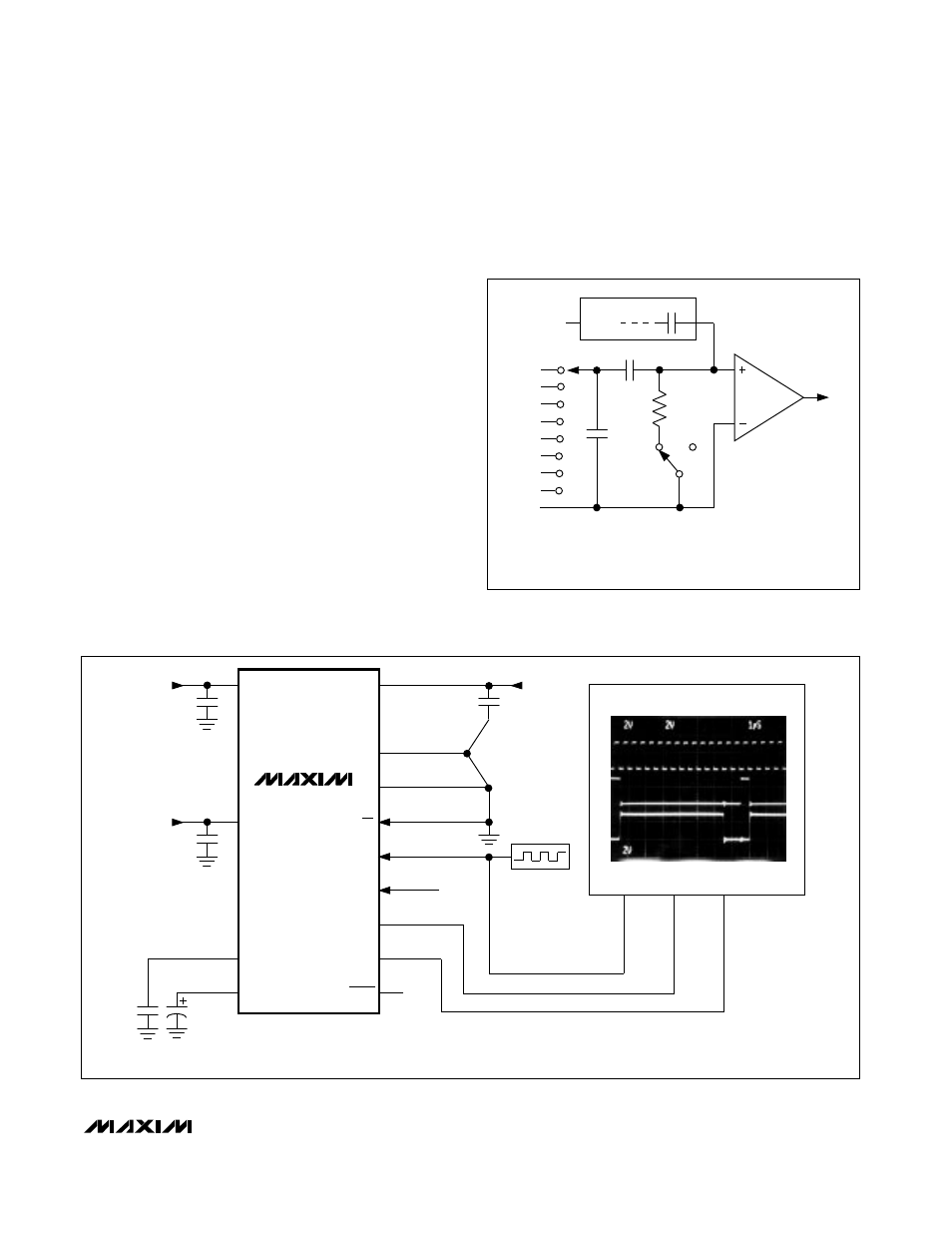
Track/Hold
The T/H enters tracking mode on the falling clock edge
after the fifth bit of the 8-bit control word is shifted in. The
T/H enters hold mode on the falling clock edge after the
eighth bit of the control word is shifted in. IN- is connect-
ed to GND if the converter is set up for single-ended
inputs, and the converter samples the “+” input. IN- con-
nects to the “-” input if the converter is set up for differen-
tial inputs, and the difference of
|N+ - IN-
is sampled.
The positive input connects back to IN+ at the end of
the conversion, and C
HOLD
charges to the input signal.
The time required for the T/H to acquire an input signal is
a function of how quickly its input capacitance is
charged. If the input signal’s source impedance is high,
acquisition time increases and more time must be
allowed between conversions. The acquisition time,
t
ACQ
, is the maximum time the device takes to acquire
the signal, and is also the minimum time needed for the
signal to be acquired. It is calculated by the following:
t
ACQ
= 7 x (R
S
+ R
IN
) x 16pF
where R
IN
= 9k
Ω
, R
S
= the source impedance of the
input signal, and t
ACQ
is never less than 1.5µs. Note that
source impedances below 4k
Ω
do not significantly affect
the ADC’s AC performance. Higher source impedances
can be used if an input capacitor is connected to the
analog inputs, as shown in Figure 5. Note that the input
capacitor forms an RC filter with the input source imped-
ance, limiting the ADC’s signal bandwidth.
Figure 5. Quick-Look Circuit
CH0
CH1
CH2
CH3
CH4
CH5
CH6
CH7
GND
C
SWITCH
TRACK
T/H
SWITCH
9k
R
IN
C
HOLD
HOLD
CAPACITIVE DAC
REF
ZERO
COMPARATOR
–
+
16pF
SINGLE-ENDED MODE:
DIFFERENTIAL MODE:
IN+ = CHO–CH7, IN- = GND.
IN+ AND IN- SELECTED FROM PAIRS OF
CH0/CH1, CH2/CH3, CH4/CH5, CH6/CH7.
AT THE SAMPLING INSTANT,
THE MUX INPUT SWITCHES
FROM THE SELECTED IN+
CHANNEL TO THE SELECTED
IN– CHANNEL.
INPUT
MUX
0.1µF
V
DD
GND
V
SS
CS
SCLK
DIN
DOUT
SSTRB
SHDN
+3V
N.C.
0.01µF
CH7
VL
REFADJ
REF
C2
0.01µF
C1
4.7µF
0V TO
4.096V
ANALOG
INPUT
0.1µF
+3V
OSCILLOSCOPE
CH1
CH2
CH3
CH4
FULL-SCALE ANALOG INPUT
MAX1204
+5V
2MHz
OSCILLATOR
SCLK
SSTRB
DOUT
Figure 4. Equivalent Input Circuit