Rainbow Electronics MAX1204 User Manual
Page 11
MAX1204
5V, 8-Channel, Serial, 10-Bit ADC
with 3V Digital Interface
______________________________________________________________________________________
11
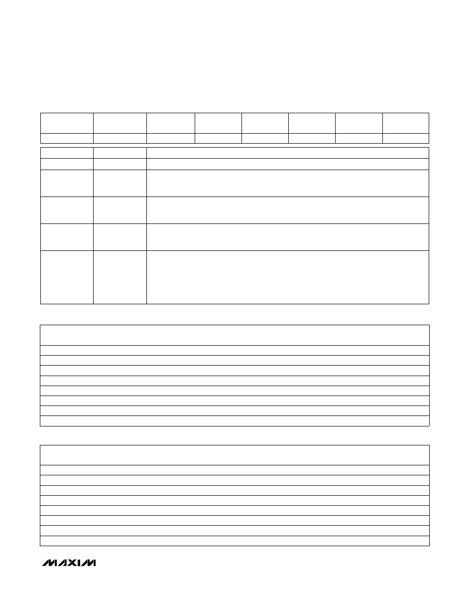
Table 2. Control-Byte Format
Table 3. Channel Selection in Single-Ended Mode (SGL/
DIF
= 1)
SEL1
SEL0
0
0
0
CH4
CH5
SEL2
CH6
CH7
GND
–
1
0
0
–
+
0
0
1
–
+
1
0
CH0
+
1
–
+
0
1
CH1
0
+
–
1
1
CH3
0
+
–
0
1
CH2
1
+
–
1
1
1
+
–
Table 4. Channel Selection in Differential Mode (SGL/
DIF
= 0)
SEL1
SEL0
0
0
0
CH4
CH5
SEL2
CH6
CH7
0
0
1
–
+
0
1
0
+
–
0
1
CH0
+
1
+
–
1
0
CH1
–
0
–
+
1
0
CH3
1
+
–
1
1
CH2
0
–
+
1
1
1
–
+
PD0
Bit 0
(LSB)
SGL/
DIF
Bit 2
PD1
Bit 1
UNI/
BIP
Bit 3
SEL 0
Bit 4
Bit 7
(MSB)
SEL 1
SEL 2
START
Bit 5
Bit 6
1
= unipolar,
0
= bipolar. Selects unipolar or bipolar conversion mode. In unipolar mode, an
analog input signal from 0V to V
REF
can be converted; in bipolar mode, the signal can range
from -V
REF
/ 2 to +V
REF
/ 2.
1
= single ended,
0
= differential. Selects single-ended or differential conversions. In single-
ended mode, input signal voltages are referred to GND. In differential mode, the voltage dif-
ference between two channels is measured. (Tables 3 and 4.)
Selects clock and power-down modes.
PD1
PD0
Mode
0
0
Full power-down (I
DD
= 2µA, internal reference)
0
1
Fast power-down (I
DD
= 30µA, internal reference)
1
0
Internal clock mode
1
1
External clock mode
These three bits select which of the eight channels is used for the conversion
(Tables 3 and 4).
The first logic
1
bit after
CS goes low defines the beginning of the control byte.
Description
Name
Bit
UNI/
BIP
3
SGL/
DIF
2
PD1
PD0
1
0 (LSB)
SEL2
SEL1
SEL0
6
5
4
START
7 (MSB)