Rainbow Electronics MAX1314 User Manual
Page 22
MAX1304–MAX1306/MAX1308–MAX1310/MAX1312–MAX1314
8-/4-/2-Channel, 12-Bit, Simultaneous-Sampling ADCs
with ±10V, ±5V, and 0 to +5V Analog Input Ranges
22
______________________________________________________________________________________
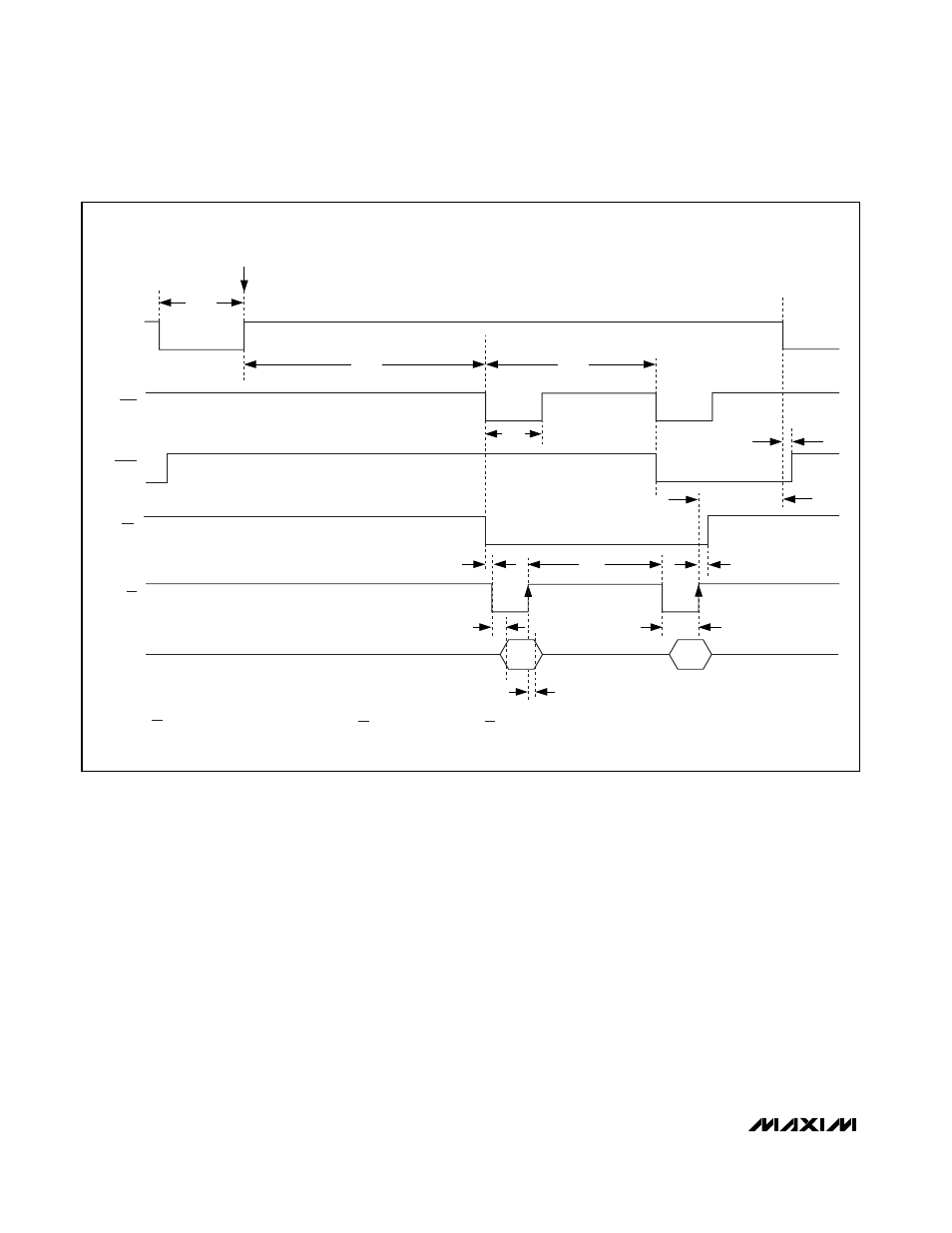
Starting a Conversion
To start a conversion using internal clock mode, pull
CONVST low for the acquisition time (t
ACQ
). The T/H
acquires the signal while CONVST is low, and conver-
sion begins on the rising edge of CONVST. The end-of-
conversion signal (EOC) pulses low whenever a
conversion result becomes available for read. The end-
of-last-conversion signal (EOLC) goes low when the last
conversion result is available (Figure 7).
To start a conversion using external clock mode, pull
CONVST low for the acquisition time (t
ACQ
). The T/H
acquires the signal while CONVST is low. The rising
edge of CONVST is the sampling instant. Apply an
external clock to CLK to start the conversion. To avoid
T/H droop degrading the sampled analog input signals,
the first CLK pulse must occur within 10µs from the
rising edge of CONVST. Additionally, the external clock
frequency must be greater than 100kHz to avoid T/H
droop-degrading accuracy. The first conversion result
is available for read when EOC goes low on the rising
edge of the 13th clock cycle. Subsequent conversion
results are available after every third clock cycle there-
after (Figures 8 and 9).
In both internal and external clock modes, hold
CONVST high until the last conversion result is read. If
CONVST goes low in the middle of a conversion, the
current conversion is aborted and a new conversion is
initiated. Furthermore, there must be a period of bus
inactivity (t
QUIET
) for 50ns or longer before the falling
edge of CONVST for the specified ADC performance.
CONVST
CH0
TRACK
HOLD
D0–D11
SAMPLE
INSTANT
t
ACQ
t
EOC
t
ACC
t
CTR
t
RDH
t
RTC
t
RDL
t
REQ
TRACK
CH1
t
CONV
t
NEXT
EOC
t
CVEOLCD
t
QUIET
≥ 50ns
EOLC
CS*
RD
*CS CAN BE LOW AT ALL TIMES, LOW DURING THE RD CYCLES, OR THE SAME AS RD.
Figure 7. Read During Conversion—Channel 0 and Channel 1 Selected, Internal Clock