Detailed description, Pin description (continued) – Rainbow Electronics MAX1314 User Manual
Page 15
MAX1304–MAX1306/MAX1308–MAX1310/MAX1312–MAX1314
8-/4-/2-Channel, 12-Bit, Simultaneous-Sampling ADCs
with ±10V, ±5V, and 0 to +5V Analog Input Ranges
______________________________________________________________________________________
15
Detailed Description
The MAX1304–MAX1306/MAX1308–MAX1310/MAX1312–
MAX1314 are 12-bit ADCs. The devices offer 8, 4, or 2
independently selectable input channels, each with
dedicated T/H circuitry. Simultaneous sampling of all
active channels preserves relative phase information
making these devices ideal for motor control and power
monitoring. Three input ranges are available, 0 to +5V,
±5V and ±10V. The 0 to +5V devices provide ±6V fault-
tolerant inputs. The ±5V and ±10V devices provide
±16.5V fault-tolerant inputs. Two-channel conversion
results are available in 0.9µs. Conversion results from
all eight channels are available in 1.98µs. The 8-chan-
nel throughput is 456ksps per channel. Internal or
external reference and clock capability offer great flexi-
bility, and ease of use. A write-only configuration regis-
ter can mask out unused channels and a shutdown
feature reduces power. A 20MHz, 12-bit, parallel data
bus outputs the conversion results. Figure 2 shows the
functional diagram of these ADCs.
100pF
DEVICE PIN
V
DD
I
OL
= 1.6mA
I
OH
= 0.8mA
1.6V
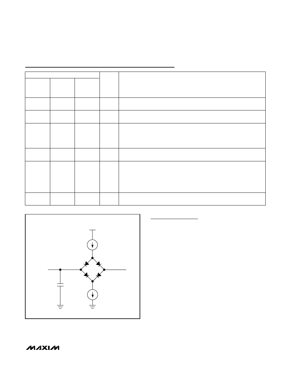
Figure 1. Digital Load Test Circuit
Pin Description (continued)
PIN
MAX1304
MAX1308
MAX1312
MAX1305
MAX1309
MAX1313
MAX1306
MAX1310
MAX1314
NAME
FUNCTION
44
44
44
CS
Chip-Select Input.
Pulling CS low activates the digital interface.
Forcing CS high
places D0–D11 in high-impedance mode.
45
45
45
C ON V S T
Conversion Start Input. Driving CONVST high initiates the conversion process.
The analog inputs are sampled on the rising edge of CONVST.
46
46
46
CLK
External Clock Input.
For external clock operation, connect INTCLK/EXTCLK to
DGND and drive CLK with an external clock signal from 100kHz to 20MHz.
For
internal clock operation, connect INTCLK/EXTCLK to DV
DD
and connect CLK to
DGND.
47
47
47
SHDN
Shutdown Input. Driving SHDN high initiates device shutdown. Connect SHDN
to DGND for normal operation.
48
48
48
CHSHDN
Active-Low Analog-Input Channel-Shutdown Input.
Drive CHSHDN low to
power down analog inputs that are not selected for conversion in the
configuration register.
Drive CHSHDN high to power up all analog input
channels regardless of whether they are selected for conversion in the
configuration register.
See the Channel Shutdown (CHSHDN)
section for more
information.
—
9, 10,
11, 12
7, 8, 9,
10, 11, 12
I.C.
Internally connected. Connect I.C. to AGND.