Parameter definitions – Rainbow Electronics MAX1211 User Manual
Page 28
Route high-speed digital signal traces away from the
sensitive analog traces. Keep all signal lines short and
free of 90
° turns.
Ensure that the differential analog input network layout is
symmetric and that all parasitics are balanced equally.
Refer to the MAX1211 evaluation kit data sheet for an
example of symmetric input layout.
Parameter Definitions
Integral Nonlinearity (INL)
Integral nonlinearity is the deviation of the values on an
actual transfer function from a straight line. This straight
line is either a best-straight-line fit or a line drawn
between the end points of the transfer function, once
offset and gain errors have been nullified. The static lin-
earity parameters for the MAX1211 are guaranteed by
design using the best-straight-line fit method.
Differential Nonlinearity (DNL)
Differential nonlinearity is the difference between an
actual step width and the ideal value of 1 LSB. A DNL
error specification of less than 1 LSB guarantees no
missing codes and a monotonic transfer function.
Offset Error
Ideally, the midscale MAX1211 transition occurs at 0.5
LSB above midscale. The offset error is the amount of
deviation between the measured transition point and
the ideal transition point.
Gain Error
Ideally, the positive full-scale MAX1211 transition
occurs at 1.5 LSB below positive full scale, and the
negative full-scale transition occurs at 0.5 LSB above
negative full scale. The gain error is the difference of
the measured transition points minus the difference of
the ideal transition points.
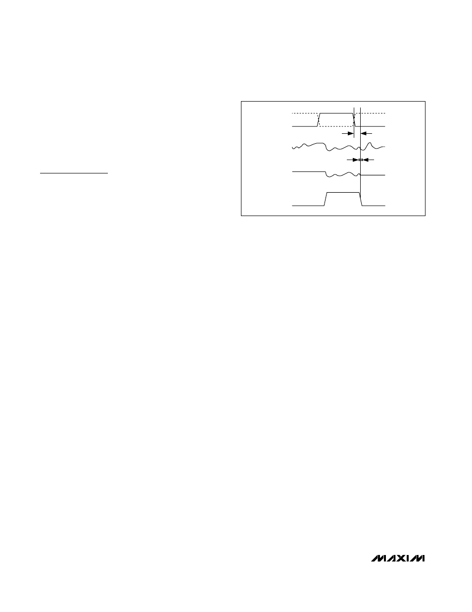
Aperture Jitter
Figure 14 depicts the aperture jitter (t
AJ
), which is the
sample-to-sample variation in the aperture delay.
Aperture Delay
Aperture delay (t
AD
) is the time defined between the
rising edge of the sampling clock and the instant when
an actual sample is taken (Figure 14).
Overdrive Recovery Time
Overdrive recovery time is the time required for the
ADC to recover from an input transient that exceeds the
full-scale limits. The MAX1211 specifies overdrive
recovery time using an input transient that exceeds the
full-scale limits by ±10%.
Signal-to-Noise Ratio (SNR)
For a waveform perfectly reconstructed from digital
samples, the theoretical maximum SNR is the ratio of
the full-scale analog input (RMS value) to the RMS
quantization error (residual error). The ideal, theoretical
minimum analog-to-digital noise is caused by quantiza-
tion error only and results directly from the ADC’s reso-
lution (N bits):
SNR
dB[max]
= 6.02
dB
× N + 1.76
dB
In reality, there are other noise sources besides quanti-
zation noise: thermal noise, reference noise, clock jitter,
etc. SNR is computed by taking the ratio of the RMS
signal to the RMS noise. RMS noise includes all spec-
tral components to the Nyquist frequency excluding the
fundamental, the first six harmonics (HD2–HD7), and
the DC offset.
MAX1211
65Msps, 12-Bit, IF Sampling ADC
28
______________________________________________________________________________________
t
AD
T/H
TRACK
HOLD
HOLD
CLKN
CLKP
ANALOG
INPUT
SAMPLED
DATA
t
AJ
Figure 14. T/H Aperture Timing