Chip information, Pin configuration, Intermodulation distortion (imd) – Rainbow Electronics MAX1207 User Manual
Page 28: 3rd-order intermodulation (im3)
MAX1207
65Msps, 12-Bit ADC
28
______________________________________________________________________________________
Intermodulation Distortion (IMD)
IMD is the ratio of the RMS sum of the intermodulation
products to the RMS sum of the two fundamental input
tones. This is expressed as:
The fundamental input tone amplitudes (V
1
and V
2
)
are at -7dBFS. Fourteen intermodulation products
(V
IMP_
) are used in the MAX1207 calculation. The
intermodulation products are the amplitudes of the
output spectrum at the following frequencies:
• 2nd-order intermodulation products: f1 + f2, f2 - f1
• 3rd-order intermodulation products: 2 x f1 - f2, 2 x f2
- f1, 2 x f1 + f2, 2 x f2 + f1
• 4th-order intermodulation products: 3 x f1 - f2, 3 x f2
- f1, 3 x f1 + f2, 3 x f2 + f1
• 5th-order intermodulation products: 3 x f1 - 2 x f2, 3
x f2 - 2 x f1, 3 x f1 + 2 x f2, 3 x f2 + 2 x f1
3rd-Order Intermodulation (IM3)
IM3 is the total power of the 3rd-order intermodulation
products to the Nyquist frequency relative to the total
input power of the two input tones f1 and f2. The indi-
vidual input tone levels are at -7dBFS. The 3rd-order
intermodulation products are 2 x f1 - f2, 2 x f2 - f1, 2 x
f1 + f2, 2 x f2 + f1.
Chip Information
TRANSISTOR COUNT: 18,700
PROCESS: CMOS
IMD
x
V
V
V
V
V
IMP
IMP
IMPn
=
+
+
+
• • • •
20
1
2
2
2
2
1
2
2
2
log
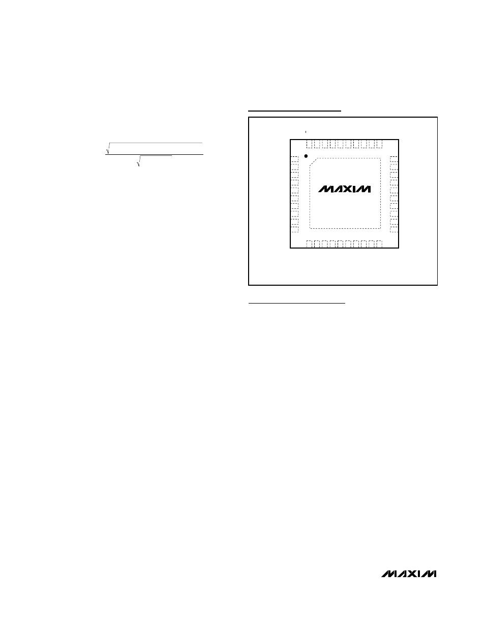
D0
D1
EXPOSED PADDLE (GND)
D3
D4
D7
D8
D9
D5
D6
D2
COM
GND
INP
INN
GND
DCE
CLKN
CLKP
REFN
REFP
1
2
3
4
5
6
7
8
9
10
11
12
13
14
15
16
17
18
19
20
40
39
38
37
36
35
34
33
32
31
30
29
28
27
26
25
24
23
22
21
V
DD
GND
OV
DD
D11
D10
V
DD
V
DD
V
DD
CLKTYP
REFIN
REFOUT
PD
V
DD
GND
OV
DD
DAV
I.C.
I.C.
G/T
THIN QFN
6mm × 6mm × 0.8mm
MAX1207
DOR
TOP VIEW
Pin Configuration