Power-down sequencing – Rainbow Electronics MAX188 User Manual
Page 17
MAX186/MAX188
Low-Power, 8-Channel,
Serial 12-Bit ADCs
______________________________________________________________________________________
17
FULL
POWER-DOWN
POWERED
UP
POWERED UP
DATA VALID
DATA VALID
INTERNAL CLOCK MODE
S X X X X X 1 0
S
0 0
X
X
X
X
X
S
MODE
DOUT
DIN
CLOCK
MODE
SETS INTERNAL
CLOCK MODE
SETS FULL
POWER-DOWN
CONVERSION
CONVERSION
SSTRB
1
0 0
DIN
REFADJ
VREF
2.5V
0V
4V
0V
1
0 1
1
1
1
1
0 0
1
0 1
FULLPD
FASTPD
NOPD
FULLPD
FASTPD
2ms WAIT
COMPLETE CONVERSION SEQUENCE
t
BUFFEN
≈
15µs
τ
= RC = 20k
Ω
x C
REFADJ
(ZEROS)
CH1
CH7
(ZEROS)
Hardware Power-Down
The
SHDN pin places the converter into the full
power-down mode. Unlike with the software shut-down
modes, conversion is not completed. It stops coinci-
dentally with
SHDN being brought low. There is no
power-up delay if an external reference is used and is
not shut down. The
SHDN pin also selects internal or
external reference compensation (see Table 7).
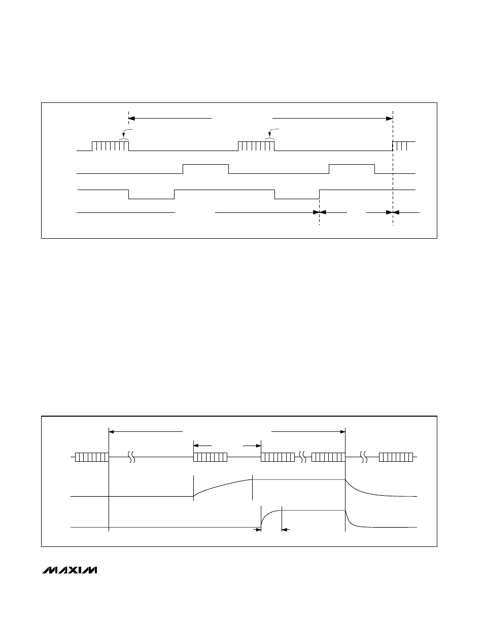
Power-Down Sequencing
The MAX186/MAX188 auto power-down modes can
save considerable power when operating at less than
maximum sample rates. The following discussion illus-
trates the various power-down sequences.
Lowest Power at up to 500
Conversions/Channel/Second
The following examples illustrate two different power-down
sequences. Other combinations of clock rates, compen-
sation modes, and power-down modes may give lowest
power consumption in other applications.
Figure 14a depicts the MAX186 power consumption for
one or eight channel conversions utilizing full
power-down mode and internal reference compensation.
A 0.01µF bypass capacitor at REFADJ forms an RC filter
with the internal 20k
Ω
reference resistor with a 0.2ms
time constant. To achieve full 12-bit accuracy, 10 time
constants or 2ms are required after power-up. Waiting
2ms in FASTPD mode instead of full power-up will reduce
the power consumption by a factor of 10 or more. This is
achieved by using the sequence shown in Figure 13.
Figure 12b. Timing Diagram Power-Down Modes, Internal Clock
Figure 13. MAX186 FULLPD/FASTPD Power-Up Sequence