Isd5100 – series – Rainbow Electronics ISD5100 User Manual
Page 83
ISD5100 – SERIES
Publication Release Date: October, 2003
- 83 -
Revision 0.2
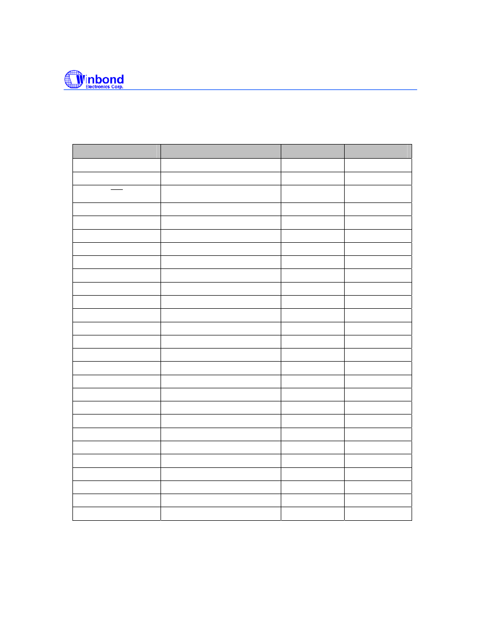
ISD5104 Pad Coordinates
(with respect to die center in µm)
Pad
Pad Name
X Axis
Y Axis
V
SSA
Analog
Ground
1882.4 2306.65
RAC
Row Address Clock
1539.15
2306.65
INT
Interrupt 790.35
2306.65
XCLK
External Clock Input
478.55
2306.65
V
CCD
Digital Supply Voltage
291.55
2306.65
V
CCD
Digital Supply Voltage
76.15
2306.65
SCL
Serial Clock Line
-198.45
2306.65
A1 Address
1
-557.95 2306.65
SDA
Serial Data Address
-815.25
2306.65
A0 Address
0
-1366.45
2306.65
V
SSD
Digital
Ground
-1839.95 2306.65
V
SSD
Digital
Ground
-1668.35 2306.65
V
SSA
Analog
Ground
-1945.05 -2311.60
MIC+ Non-inverting
Microphone Input
-1739.25 -2311.60
MIC- Inverting
Microphone Input
-1506.75 -2311.60
ANA OUT+
Non-inverting Analog Output
-1245.05
-2311.60
ANA OUT-
Inverting Analog Output
-910.85
-2311.60
ACAP AGC/AutoMute
Cap
-623.55 -2311.60
SP- Speaker
Negative -127.75
-2311.60
V
SSA
Analog
Ground
205.85 -2311.60
V
SSA
Analog
Ground
295.85 -2311.60
SP+ Speaker
Positive
629.45 -2311.60
V
CCA
Analog Supply Voltage
963.05
-2311.60
V
CCA
Analog Supply Voltage
1053.05
-2311.60
ANA IN
Analog Input
1260.35
-2311.60
AUX IN
Auxiliary Input
1525.95
-2311.60
AUX OUT
Auxiliary Output
1770.15
-2311.60