Isd5100 – series – Rainbow Electronics ISD5100 User Manual
Page 49
ISD5100 – SERIES
Publication Release Date: October, 2003
- 49 -
Revision 0.2
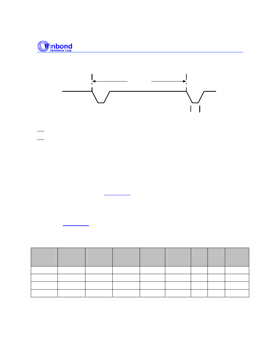
RAC Waveform During Digital Erase @ 8kHz Operation
1.25 ms
TRACE
.25 ms
T
RACEL
INT
(Interrupt)
INT
is an open drain output pin. The ISD5100 Series interrupt pin goes LOW and stays LOW when an
Overflow (OVF) or End of Message (EOM) marker is detected. Each operation that ends in an EOM or
OVF generates an interrupt, including the message cueing cycles. The interrupt is cleared by a READ
STATUS instruction that will give a status byte out the SDA line.
XCLK (External Clock Input)
The external clock input for the ISD5100 Series product has an internal pull-down device. Normally,
the ISD5100 Series are operated at one of four internal rates selected for its internal oscillator by the
Sample Rate Select bits. If greater precision is required, the device can be clocked through the XCLK
pin at 4.096 MHz as described in
section 7.4.3
on page 32.
Because the anti-aliasing and smoothing filters track the Sample Rate Select bits, one must, for
optimum performance, maintain the external clock at 4.096 MHz AND set the Sample Rate
Configuration bits to one of the four values to properly set the filters to the correct cutoff frequency as
described in
section 7.4.3
on page 32. The duty cycle on the input clock is not critical, as the clock is
immediately divided by two internally. If the XCLK is not used, this input should be connected to V
SSD
.
External Clock Input Table
ISD5116
Duration
(Minutes)
ISD5108
Duration
(Minutes)
ISD5104
Duration
(Minutes)
ISD5102
Duration
(Minutes)
Sample
Rate
(kHz)
Required
Clock
(kHz)
FLD1 FLD0
Filter
Knee
(kHz)
8.73 4.36 2.18 1.08 8.0 4096
0
0 3.4
10.9 5.45 2.72 1.35 6.4 4096
0
1 2.7
13.1 6.55 3.27 1.63 5.3 4096
1
0 2.3
17.5 8.75 4.37 2.18 4.0 4096
1
1 1.7