Isd5100 – series – Rainbow Electronics ISD5100 User Manual
Page 28
ISD5100 – SERIES
- 28 -
7.4. A
NALOG
M
ODE
7.4.1. Aux In and Ana In Description
The AUX IN is an additional audio input to the ISD5100-Series, such as from the microphone circuit in
a mobile phone “car kit.” This input has a nominal 694 mV p-p level at its minimum gain setting (0 dB).
See the
AUX IN Amplifier Gain Settings table
on page 37. Additional gain is available in 3 dB steps
(controlled by the I
2
C serial interface) up to 9 dB.
The ANA IN pin is the analog input from the telephone chip set. It can be switched (by the serial bus)
to the speaker output, the array input or to various other paths. This pin is designed to accept a
nominal 1.11 Vp-p when at its minimum gain (6 dB) setting. See the
ANA IN Amplifier Gain Settings
table
on page 37. There is additional gain available in 3 dB steps controlled from the I
2
C interface, if
required, up to 15 dB.
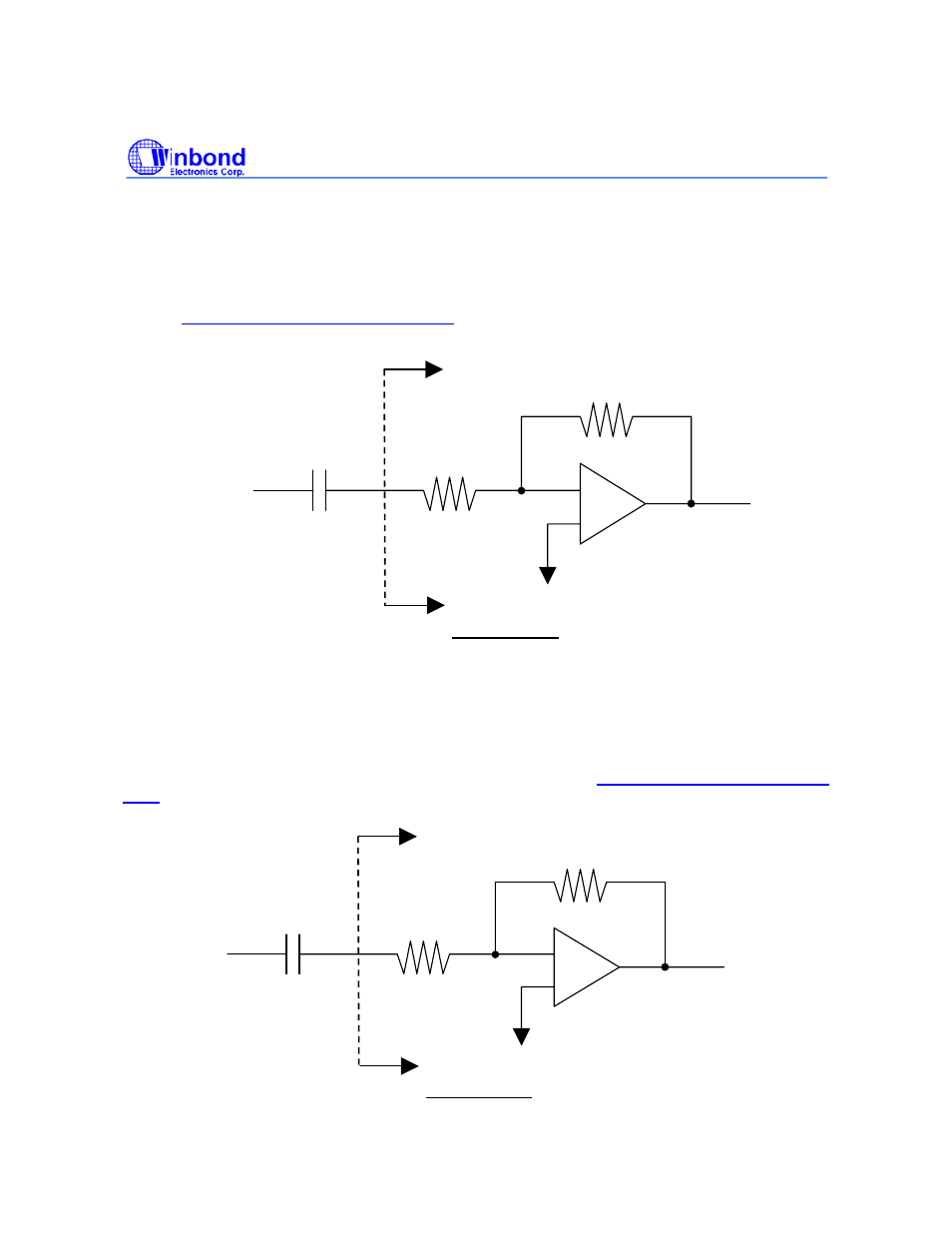
AUX IN
Input Amplifier
AUX IN
Input
C
COUP
=0.1
µF
Ra
Rb
Internal to the device
NOTE: f
CUTOFF
=
2
πRaC
COUP
1
ANA IN
Input Amplifier
ANA IN
Input
C
COUP
=0.1
µF
Ra
Rb
Internal to the device
NOTE: f
CUTOFF
=
2
πRaC
COUP
1