Isd5100 – series – Rainbow Electronics ISD5100 User Manual
Page 15
ISD5100 – SERIES
Publication Release Date: October, 2003
- 15 -
Revision 0.2
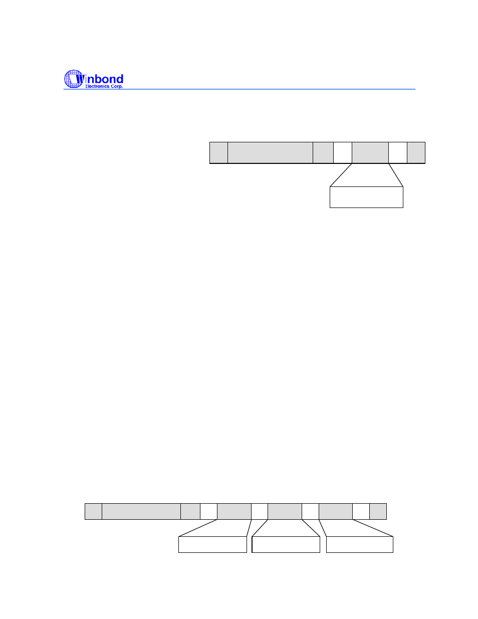
7.3.1.2. Load Command Byte Register (Single Byte Load):
A single byte may be written to the Command Byte Register in order to power up the device, start
or stop Analog Record (if no address information is needed), or do a Message Cueing function.
The Command Byte Register is loaded as follows:
1. Host executes I
2
C START
2. Send Slave Address with R/W bit = “0” (Write) [80h]
3. Slave responds back with an ACK.
4. Wait for SCL to go HIGH
5. Host sends a command byte to Slave
6. Slave responds with an ACK
7. Wait for SCL to go HIGH
8. Host executes I
2
C STOP
7.3.1.3. Load Command Byte Register (Address Load)
For the normal addressed mode the Registers are loaded as follows:
1. Host executes I
2
C START
2. Send Slave Address with R/W bit = “0” (Write)
3. Slave responds back with an ACK.
4. Wait for SCL to go HIGH
5. Host sends a byte to Slave - (Command Byte)
6. Slave responds with an ACK
7. Wait for SCL to go HIGH
8. Host sends a byte to Slave - (High Address Byte)
9. Slave responds with an ACK
10. Wait for SCL to go HIGH
11. Host sends a byte to Slave - (Low Address Byte)
12. Slave responds with an ACK
13. Wait for SCL to go HIGH
14. Host executes I
2
C STOP
S
SLAVE ADDRESS
A
DATA
P
W
Command Byte
A
S
SLAVE ADDRESS
A
P
W
Command
DATA
A
DATA
A
DATA
A
High Addr.
Low Addr.