Isd5100 – series – Rainbow Electronics ISD5100 User Manual
Page 57
ISD5100 – SERIES
Publication Release Date: October, 2003
- 57 -
Revision 0.2
I
2
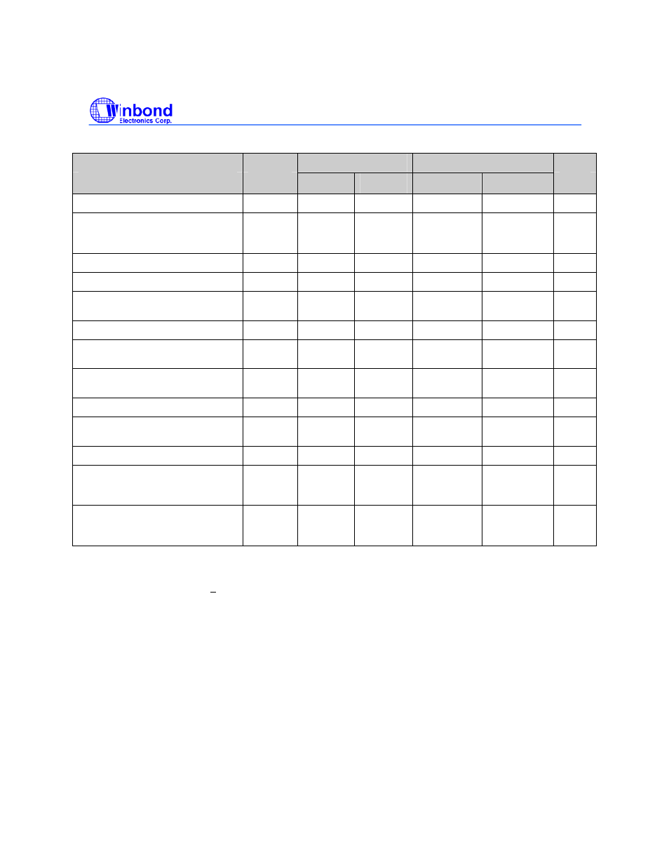
C INTERFACE TIMING
STANDARD-MODE
FAST-MODE
PARAMETER
SYMBOL
MIN.
MAX.
MIN.
MAX.
UNIT
SCL clock frequency
f
SCL
0 100 0
400
kHz
Hold time (repeated) START
condition. After this period, the first
clock pulse is generated
t
HD-STA
4.0 - 0.6
- µs
LOW period of the SCL clock
t
LOW
4.7 - 1.3
- µs
HIGH period of the SCL clock
t
HIGH
4.0 - 0.6
- µs
Set-up time for a repeated START
condition
t
SU-STA
4.7 - 0.6
- µs
Data set-up time
t
SU-DAT
250 - 100
(1)
-
ns
Rise time of both SDA and SCL
signals
t
r
-
1000
20 + 0.1C
b
(2)
300 ns
Fall time of both SDA and SCL
signals
t
f
-
300
20 + 0.1C
b
(2)
300 ns
Set-up time for STOP condition
t
SU-STO
4.0 - 0.6
- µs
Bus-free time between a STOP and
START condition
t
BUF
4.7 - 1.3
- µs
Capacitive load for each bus line
C
b
- 400 -
400 pF
Noise margin at the LOW level for
each connected device (including
hysteresis)
V
nL
0.1 V
DD
- 0.1
V
DD
- V
Noise margin at the HIGH level for
each connected device (including
hysteresis)
V
nH
0.2 V
DD
- 0.2
V
DD
- V
1. A Fast-mode I
2
C-interface device can be used in a Standard-mode I
2
C-interface system, but the
requirement t
SU;DAT
> 250 ns must then be met. This will automatically be the case if the device does not
stretch the LOW period of the SCL signal.
If such a device does stretch the LOW period of the SCL signal, it must output the next data bit to the SDA
line; t
r max
+ t
SU;DAT
= 1000 + 250 = 1250 ns (according to the Standard-mode I
2
C -interface specification)
before the SCL line is released.
2. C
b
= total capacitance of one bus line in pF. If mixed with HS mode devices, faster fall-times are
allowed.