Isd5100 – series – Rainbow Electronics ISD5100 User Manual
Page 35
ISD5100 – SERIES
Publication Release Date: October, 2003
- 35 -
Revision 0.2
1. Gain from ANA IN to SP+/-
2. Gain from ANA IN to ARRAY IN
3. 0TLP Input is the reference Transmission Level Point that is used for testing. This level is
typically 3 dB below clipping
4. Speaker Out gain set to 1.6 (High). (Differential)
AUX IN (Auxiliary Input)
The AUX IN is an additional audio input to the ISD5100-Series, such as from the microphone circuit in
a mobile phone “car kit.” This input has a nominal 694 mV p-p level at its minimum gain setting (0 dB).
See the following table. Additional gain is available in 3 dB steps (controlled by the I
2
C interface) up to
9 dB.
AUX IN Input Modes
AUX IN Amplifier Gain Settings
CFG0
Setting
(1)
0TLP
Input
V
P-P
(3)
AXG1 AXG0
Gain
(2)
Array
In/Out V
P-P
Speaker
Out V
P-P
(4)
0 dB
0.694
0
0
1.00
0.694
0.694
3 dB
0.491
0
1
1.41
0.694
0.694
6 dB
0.347
1
0
2.00
0.694
0.694
9 dB
0.245
1
1
2.82
0.694
0.694
1. Gain from AUX IN to ANA OUT
2. Gain from AUX IN to ARRAY IN
3. 0TLP Input is the reference Transmission Level Point that is used for testing. This level is typically
3 dB below clipping
4.
Differential
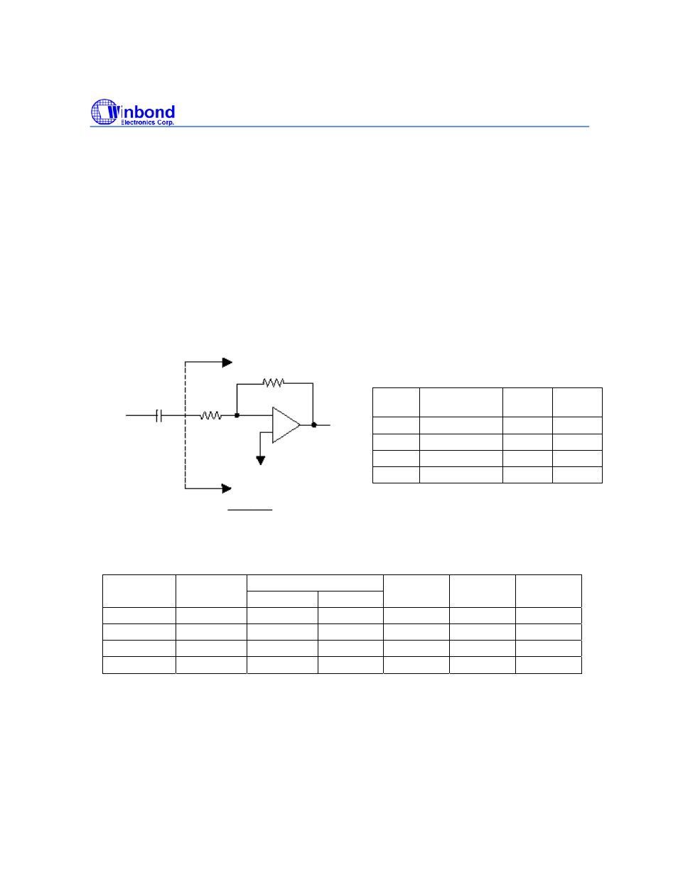
Gain
Setting
Resistor Ratio
(Rb/Ra)
Gain Gain
(2)
(dB)
00
40.1 / 40.1
1.0
0
01
47.0 / 33.2
1.414
3
10
53.5 / 26.7
2.0
6
11
59.2 / 21
2.82
9
Note: Ra & Rb are in k
Ω
AUX IN
Input
ANA IN
Input Amplifier
NOTE:
f
CUTTOFF
2xR
a
C
COUP
1
Ra
Rb
C
COUP =
0.1
µ
F
Internal to the device