Ata6837 [preliminary – Rainbow Electronics ATA6837 User Manual
Page 6
6
4953C–AUTO–09/07
ATA6837 [Preliminary]
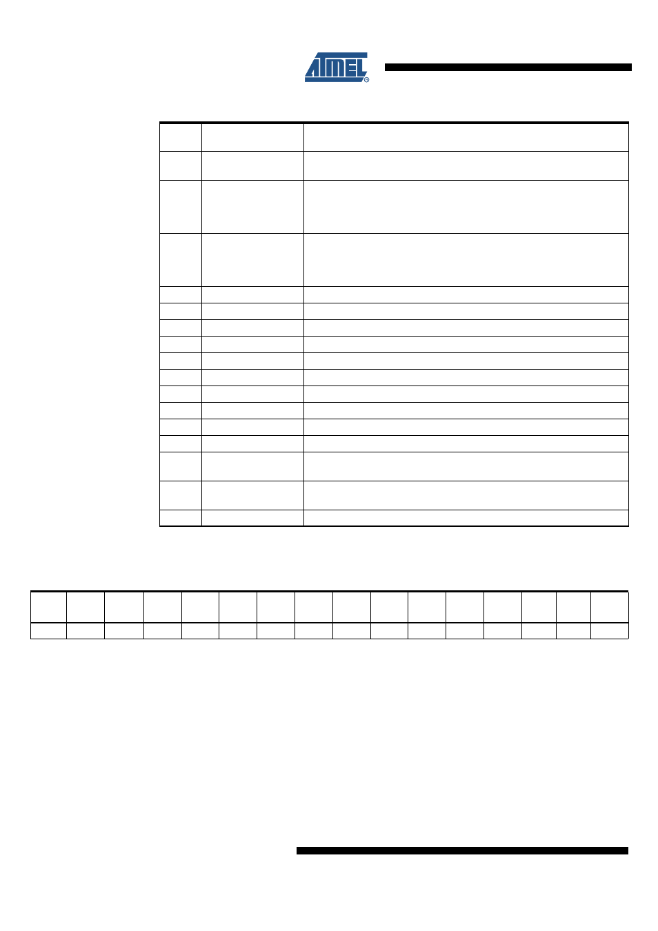
Table 3-2.
Output Data Protocol
Bit
Output (Status)
Register
Function
0
TP
Temperature prewarning: high = warning
(overtemperature shutdown see remark below)
1
Status LS1
Normal operation: high = output is on, low = output is off
Open-load detection: high = open load, low = no open load
(correct load condition is detected if the corresponding output is
switched off)
2
Status HS1
Normal operation: high = output is on, low = output is off
Open-load detection: high = open load, low = no open load
(correct load condition is detected if the corresponding output is
switched off)
3
Status LS2
Description see LS1
4
Status HS2
Description see HS1
5
Status LS3
Description see LS1
6
Status HS3
Description see HS1
7
Status LS4
Description see LS1
8
Status HS4
Description see HS1
9
Status LS5
Description see LS1
10
Status HS5
Description see HS1
11
Status LS6
Description see LS1
12
Status HS6
Description see HS1
13
SCD
Short circuit detected: set high, when at least one output is switched off
by a short circuit condition
14
INH
Inhibit: this bit is controlled by software (bit SI in input register) and
hardware inhibit (pin INH). High = standby, low = normal operation
15
PSF
Power supply fail: undervoltage at pin VS detected
Note:
Bit 0 to 15 = high: overtemperature shutdown
Table 3-3.
Status of the Input Register After Power on Reset
Bit 15
(SI)
Bit 14
(SCT)
Bit 13
(OLD)
Bit 12
(HS6)
Bit 11
(LS6)
Bit 10
(HS5)
Bit 9
(LS5)
Bit 8
(HS4)
Bit 7
(LS4)
Bit 6
(HS3)
Bit 5
(LS3)
Bit 4
(HS2)
Bit 3
(LS2)
Bit 2
(HS1)
Bit 1
(LS1)
Bit 0
(SRR)
H
H
H
L
L
L
L
L
L
L
L
L
L
L
L
L