Ds1374 i, Detailed description, Oscillator circuit – Rainbow Electronics DS1374 User Manual
Page 9: Clock accuracy, Address map, Time-of-day counter, Table 1. crystal specifications
Detailed Description
The DS1374 is a real-time clock with an I
2
C serial inter-
face. It provides elapsed seconds from a user-defined
starting point in a 32-bit counter (Figure 4). A 24-bit
counter can be configured as either a watchdog
counter or an alarm counter. An on-chip oscillator cir-
cuit uses a customer-supplied 32.768kHz crystal to
keep time. A power-control circuit switches operation
from V
CC
to V
BACKUP
and back when power on V
CC
is
cycled. If a rechargeable backup supply is used, a
trickle charger can be enabled to charge the backup
supply while V
CC
is on.
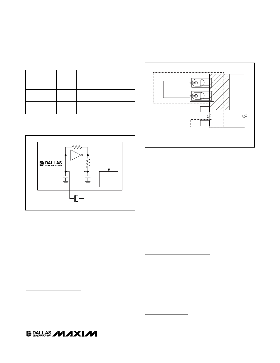
Oscillator Circuit
The DS1374 uses an external 32.768kHz crystal. The
oscillator circuit does not require any external resistors
or capacitors to operate. Table 1 specifies several crys-
tal parameters for the external crystal. Figure 5 shows a
functional schematic of the oscillator circuit. The startup
time is usually less than 1 second when using a crystal
with the specified characteristics.
Clock Accuracy
Clock accuracy is dependent upon the accuracy of the
crystal and the accuracy of the match between the
capacitive load of the oscillator circuit and the capacitive
load for which the crystal was trimmed. Additional error
is added by crystal frequency drift caused by tempera-
ture shifts. External circuit noise coupled into the oscilla-
tor circuit can result in the clock running fast. Figure 6
shows a typical PC board layout for isolating the crystal
and oscillator from noise. Refer to Application Note 58:
Crystal Considerations with Dallas Real-Time Clocks for
detailed information.
DS1374C Only
The DS1374C integrates a standard 32,768Hz crystal
into the package. Typical accuracy at nominal V
CC
and
25°C is approximately 10ppm. See Application Note 58
for information about crystal accuracy vs. temperature.
Address Map
Table 2 shows the address map for the DS1374 regis-
ters. During a multibyte access, the address pointer
wraps around to location 00h when it reaches the end of
the register space (08h). On an I
2
C START, STOP, or
address pointer incrementing to location 00h, the current
time is transferred to a second set of registers. These
secondary registers read the time information, while the
clock continues to run. This eliminates the need to reread
the registers in case of an update of the main registers
during a read.
Time-of-Day Counter
The time-of-day counter is a 32-bit up counter. The
contents can be read or written by accessing the
DS1374
I
2
C, 32-Bit Binary Counter Watchdog RTC with
Trickle Charger and Reset Input/Output
_____________________________________________________________________
9
COUNTDOWN
CHAIN
X1
X2
C
L
1
C
L
2
CRYSTAL
RTC
REGISTERS
DS1374
Figure 5. Oscillator Circuit Showing Internal Bias Network
LOCAL GROUND PLANE (LAYER 2)
NOTE: AVOID ROUTING SIGNALS IN THE CROSSHATCHED AREA (UPPER LEFT-HAND
QUADRANT) OF THE PACKAGE UNLESS THERE IS A GROUND PLANE BETWEEN THE
SIGNAL LINE AND THE PACKAGE.
CRYSTAL
GND
X2
X1
Figure 6. Layout Example
PARAMETER
SYMBOL
MIN
TYP
MAX
UNITS
Nominal
Frequency
f
O
32.768
kHz
Series
Resistance
ESR
45
k
Ω
Load
Capacitance
C
L
6
pF
Table 1. Crystal Specifications*
*The crystal, traces, and crystal input pins should be isolated
from RF generating signals. Refer to Application Note 58:
Crystal Considerations for Dallas Real-Time Clocks for addi-
tional specifications.