Ds1374 i, C serial data bus – Rainbow Electronics DS1374 User Manual
Page 13
Assume that a system power supply of 3.3V is applied
to V
CC
and a super cap is connected to V
BACKUP
. Also
assume the trickle charger has been enabled with a
diode and resistor R2 between V
CC
and V
BACKUP
. The
maximum current I
MAX
would therefore be calculated
as follows:
I
MAX
= (3.3V - diode drop) / R2
≈ (3.3V - 0.7V) / 2kΩ ≈
1.3mA
As the super cap changes, the voltage drop between
V
CC
and V
BACKUP
decreases and therefore the charge
current decreases.
I
2
C Serial Data Bus
The DS1374 supports the I
2
C bus protocol. A device
that sends data onto the bus is defined as a transmitter
and a device receiving data is a receiver. The device
that controls the message is called a master. The
devices that are controlled by the master are slaves. A
master device that generates the serial clock (SCL),
controls the bus access, and generates the START and
STOP conditions must control the bus. The DS1374
operates as a slave on the I
2
C bus. Connections to the
bus are made through the open-drain I/O lines SDA
and SCL. A standard mode (100kHz max clock rate)
and a fast mode (400kHz max clock rate) are defined
within the bus specifications. The DS1374 works in both
modes.
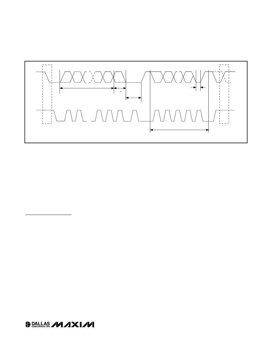
The following bus protocol has been defined (Figure 8):
• Data transfer can be initiated only when the bus is
not busy.
• During data transfer, the data line must remain sta-
ble whenever the clock line is high. Changes in the
data line while the clock line is high can be interpret-
ed as control signals.
Accordingly, the following bus conditions have been
defined:
Bus not busy: Both data and clock lines remain
high.
Start data transfer: A change in the state of the
data line from high to low, while the clock line is
high, defines a START condition.
Stop data transfer: A change in the state of the
data line from low to high, while the clock line is
high, defines a STOP condition.
Data valid: The state of the data line represents
valid data when, after a START condition, the data
line is stable for the duration of the high period of
the clock signal. The data on the line must be
changed during the low period of the clock signal.
There is one clock pulse per bit of data.
Each data transfer is initiated with a START condi-
tion and terminated with a STOP condition. The
number of data bytes transferred between the
START and the STOP conditions is not limited, and
is determined by the master device. The informa-
tion is transferred byte-wise and each receiver
acknowledges with a ninth bit. A standard mode
(100kHz clock rate) and a fast mode (400kHz clock
rate) are defined within the I
2
C bus specifications.
Acknowledge: Each receiving device, when
addressed, is obliged to generate an acknowledge
after the reception of each byte. The master device
must generate an extra clock pulse that is associat-
ed with this acknowledge bit.
DS1374
I
2
C, 32-Bit Binary Counter Watchdog RTC with
Trickle Charger and Reset Input/Output
____________________________________________________________________
13
STOP
CONDITION
OR REPEATED
START
CONDITION
REPEATED IF MORE BYTES
ARE TRANSFERED
ACK
START
CONDITION
ACK
ACKNOWLEDGEMENT
SIGNAL FROM RECEIVER
ACKNOWLEDGEMENT
SIGNAL FROM RECEIVER
SLAVE ADDRESS
MSB
SCL
SDA
R/W
DIRECTION
BIT
1
2
6
7
8
9
1
2
8
9
3–7
Figure 8. I
2
C Data Transfer Overview