Ds1374 i, Special purpose registers, Table 4. trickle charge register – Rainbow Electronics DS1374 User Manual
Page 11
Special Purpose Registers
The DS1374 has two additional registers (07h–08h) that
control the WD/
ALM counter and the square-wave, inter-
rupt, and reset outputs.
Control Register (07h)
Bit 7/Enable Oscillator (
EOSC). When set to logic 0,
the oscillator is started. When set to logic 1, the oscilla-
tor is stopped. When this bit is set to logic 1, the oscilla-
tor is stopped and the DS1374 is placed into a
low-power standby mode (I
DDR
). This bit is clear (logic
0) when power is first applied. When the DS1374 is
powered by V
CC
, the oscillator is always on regardless
of the state of the
EOSC bit.
Bit 6/WD/A
AL
LM
M Counter Enable (WACE). When set to
logic 1, the WD/
ALM counter is enabled. When set to
logic 0, the WD/
ALM counter is disabled, and the 24
bits can be used as NV RAM. This bit is clear (logic 0)
when power is first applied.
Bit 5/WD/A
AL
LM
M Counter Select (WD/
ALM). When set to
logic 0, the counter decrements every second until it
reaches zero and is then reloaded and restarted. When
set to logic 1, the WD/
ALM counter decrements every
1/4096 of a second (approximately every 244µs) until it
reaches zero, sets the AF bit in the status register, and
stops. If any of the WD/
ALM counter registers are
accessed before the counter reaches zero, the counter
is reloaded and restarted. This bit is clear (logic 0)
when power is first applied.
Bit 4/Battery-Backed Square-Wave Enable (BBSQW).
This bit, when set to logic 1, enables the square-wave
output when V
CC
is absent and when the DS1374 is
being powered by the V
BACKUP
pin. When BBSQW is
logic 0, the SQW pin goes high impedance when V
CC
falls below the power-fail trip point. This bit is disabled
(logic 0) when power is first applied.
Bit 3/Watchdog Reset Steering Bit (WDSTR). This bit
selects which output pin the watchdog-reset signal
occurs on. When the WDSTR bit is set to logic 0, a
250ms pulse occurs on the
RST pin if WD/ALM = 1 and
the WD/
ALM counter reaches zero. The 250ms reset
pulse occurs on the
INT pin when the WDSTR bit is set
to logic 1. This bit is logic 0 when power is first applied.
Bits 2, 1/Rate Select (RS2 and RS1). These bits con-
trol the frequency of the square-wave output when the
square wave has been enabled. Table 3 shows the
square-wave frequencies that can be selected with the
RS bits. These bits are both set (logic 1) when power is
first applied.
Bit 0/Alarm Interrupt Enable (AIE). When set to logic
1, this bit permits the alarm flag (AF) bit in the status
register to assert
INT (when INTCN = 1). When set to
logic 0 or INTCN is set to logic 0, the AF bit does not
initiate the
INT signal. If the WD/ALM bit is set to logic 1
and the AF flag is set, writing AIE to zero does not trun-
cate the 250ms pulse on the
INT pin. The AIE bit is at
logic 0 when power is first applied. The
INT output is
available while the device is powered by either supply.
DS1374
I
2
C, 32-Bit Binary Counter Watchdog RTC with
Trickle Charger and Reset Input/Output
____________________________________________________________________
11
TCS3
TCS2
TCS1
TCS0
DS1
DS0
ROUT1
ROUT0
FUNCTION
X
X
X
X
0
0
X
X
Disabled
X
X
X
X
1
1
X
X
Disabled
X
X
X
X
X
X
0
0
Disabled
1
0
1
0
0
1
0
1
No diode, 250
Ω resistor
1
0
1
0
1
0
0
1
One diode, 250
Ω resistor
1
0
1
0
0
1
1
0
No diode, 2k
Ω resistor
1
0
1
0
1
0
1
0
One diode, 2k
Ω resistor
1
0
1
0
0
1
1
1
No diode, 4k
Ω resistor
1
0
1
0
1
0
1
1
One diode, 4k
Ω resistor
0
0
0
0
0
0
0
0
Power-on reset value
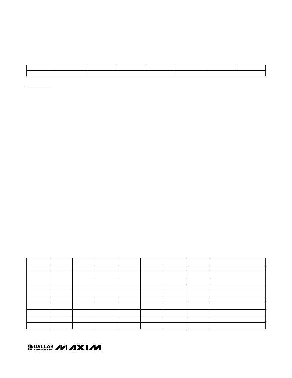
Table 4. Trickle Charge Register
Bit 7
Bit 6
Bit 5
Bit 4
Bit 3
Bit 2
Bit 1
Bit 0
EOSC
WACE
WD/
ALM
BBSQW
WDSTR
RS2
RS1
AIE