Ds1374 i – Rainbow Electronics DS1374 User Manual
Page 14
DS1374
I
2
C, 32-Bit Binary Counter Watchdog RTC with
Tickle Charger and Reset Input/Output
14
____________________________________________________________________
A device that acknowledges must pull down the
SDA line during the acknowledge clock pulse in
such a way that the SDA line is stable low during
the high period of the acknowledge-related clock
pulse. Setup and hold times must be considered. A
master must signal an end of data to the slave by
not generating an acknowledge bit on the last byte
that has been clocked out of the slave. In this case,
the slave must leave the data line high to enable
the master to generate the STOP condition.
Figures 9 and 10 detail how data transfer is accom-
plished on the 2-wire bus. Depending on the state of
the R/
W bit, two types of data transfer are possible:
Data transfer from a master transmitter to a
slave receiver. The first byte transmitted by the
master is the slave address. Next follows a number
of data bytes. The slave returns an acknowledge bit
after each received byte.
Data transfer from a slave transmitter to a mas-
ter receiver. The master transmits the first byte (the
slave address). The slave then returns an acknowl-
edge bit. Next follows a number of data bytes
transmitted by the slave to the master. The master
returns an acknowledge bit after all received bytes
other than the last byte. At the end of the last
received byte, a “not acknowledge” is returned.
The master device generates the serial clock puls-
es and the START and STOP conditions. A transfer
is ended with a STOP condition or with a repeated
START condition. Since a repeated START condi-
tion is also the beginning of the next serial transfer,
the bus is not released.
The DS1374 can operate in the following two modes:
Slave Receiver Mode (Write Mode): Serial data
and clock data are received through SDA and SCL.
After each byte is received, an acknowledge bit is
transmitted. START and STOP conditions are rec-
ognized as the beginning and end of a serial trans-
fer. Address recognition is performed by hardware
after reception of the slave address and direction
bit. The slave address byte is the first byte received
after the master generates a START condition. The
slave address byte contains the 7-bit DS1374
address, which is 1101000, followed by the direc-
tion bit (R/
W), which is zero for a write. After receiv-
ing and decoding the slave address byte, the
DS1374 outputs an acknowledge on SDA. After the
DS1374 acknowledges the slave address + write
bit, the master transmits a register address to the
DS1374. This sets the register pointer on the
DS1374, with the DS1374 acknowledging the trans-
fer. The master can then transmit zero or more
bytes of data, with the DS1374 acknowledging
each byte received. The register pointer increments
after each data byte is transferred. The master gen-
erates a STOP condition to terminate the data write.
Slave Transmitter Mode (Read Mode): The first
byte is received and handled as in the slave receiv-
er mode. However, in this mode, the direction bit
indicates that the transfer direction is reversed.
Serial data is transmitted on SDA by the DS1374,
while the serial clock is input on SCL. START and
STOP conditions are recognized as the beginning
and end of a serial transfer. Address recognition is
performed by hardware after reception of the slave
address and direction bit. The slave address byte
is the first byte received after the START condition
is generated by the master. The slave address byte
contains the 7-bit DS1374 address, which is
1101000, followed by the direction bit (R/
W), which
is 1 for a read. After receiving and decoding the
slave address byte, the DS1374 outputs an
acknowledge on SDA. The DS1374 then begins to
transmit data starting with the register address
pointed to by the register pointer. If the register
pointer is not written to before the initiation of a
read mode, the first address that is read is the last
one stored in the register pointer. The DS1374 must
receive a not acknowledge to end a read.
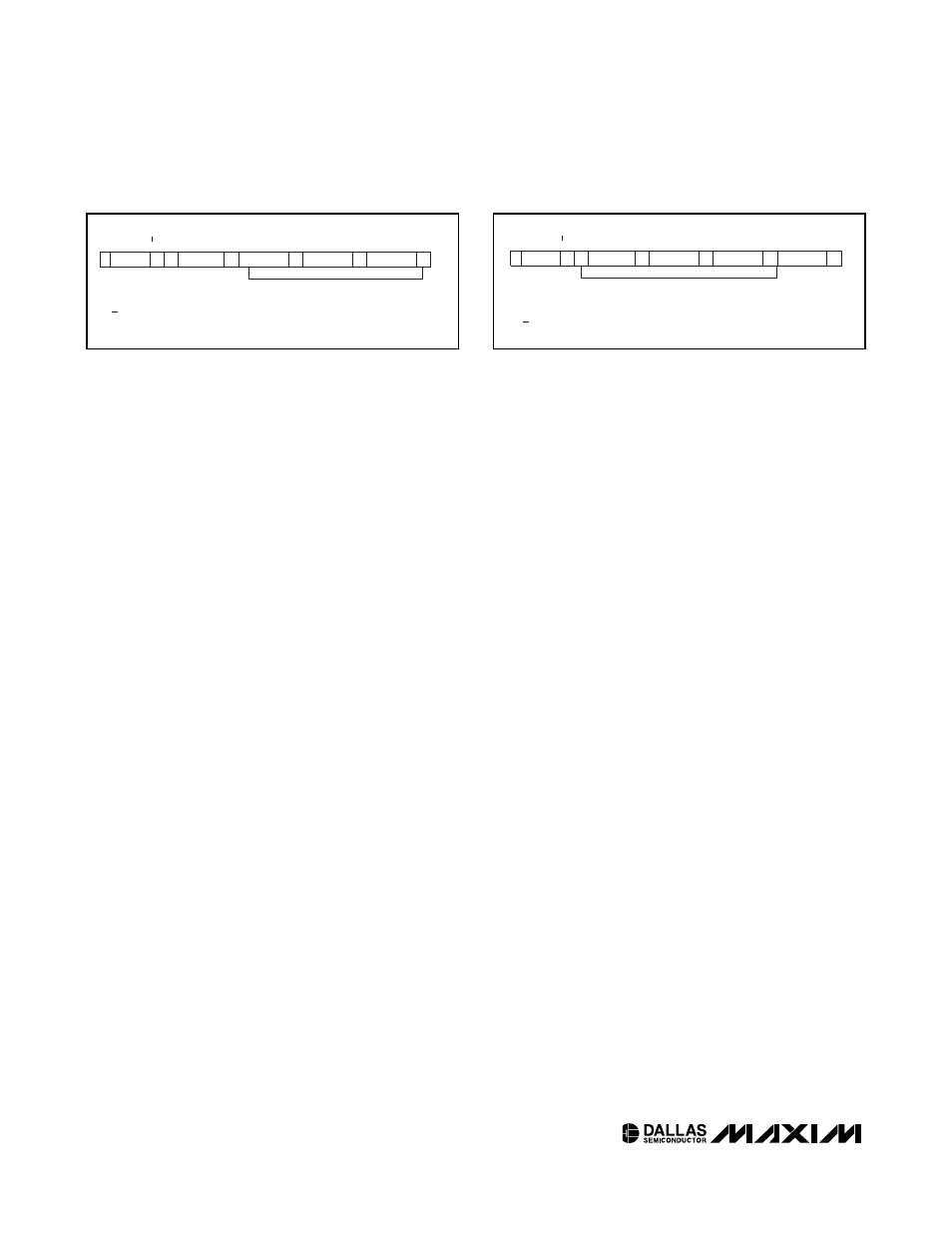
S 1101000
0 A XXXXXXXX A
XXXXXXXX
A
XXXXXXXX A
XXXXXXXX
P
DATA TRANSFERRED
(X+1 Bytes + Acknowledge)
SLAVE
ADDRESS
S - START
A - ACKNOWLEDGE
P - STOP
R/W - READ/WRITE OR
DIRECTION BIT
DATA (n)
REGISTER
ADDRESS (n)
DATA (n + 1)
DATA (n + x)
R/W
Figure 9. I
2
C Write Protocol
S 1101000
1 A XXXXXXXX A
XXXXXXXX
A
XXXXXXXX A
XXXXXXXX
/A
DATA TRANSFERRED
(X+1 Bytes + Acknowledge)
SLAVE
ADDRESS
S - START
A - ACKNOWLEDGE
P - STOP
/A - NOT ACKNOWLEDGE
R/W - READ/WRITE OR
DIRECTION BIT
DATA (n)
DATA (n + 1)
DATA (n + x)
DATA (n + 2)
R/W
Figure 10. I
2
C Read Protocol