Ata8402 – Rainbow Electronics ATA8402 User Manual
Page 3
3
4982A–IND–02/07
ATA8402
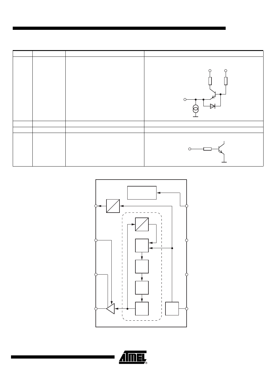
Figure 2-2.
Block Diagram
5
XTAL
Connection for crystal
6
VS
Supply voltage
See ESD protection circuitry (see
7
GND
Ground
See ESD protection circuitry (see
8
ENABLE
Enable input
Table 2-1.
Pin Description (Continued)
Pin
Symbol
Function
Configuration
1.5 k
Ω
1.2 k
Ω
182 µA
XTAL
VS
VS
200 k
Ω
ENABLE
ATA8402
CP
Power up/down
32
5
6
7
8
4
3
2
XTAL
VS
GND
ENABLE
ANT1
ANT2
PA_ENABLE
CLK
1
f
LF
PA
VCO
PLL
XTO
4
f
See also other documents in the category Rainbow Electronics Wireless Headsets:
- RC2000 (2 pages)
- Т7023 (12 pages)
- Т7024 (20 pages)
- RC2200 (17 pages)
- RF01 (26 pages)
- RC1090 (17 pages)
- U3741BM (32 pages)
- U3742BM (32 pages)
- RAM01 (7 pages)
- RF22 (92 pages)
- RC1180-MBUS (28 pages)
- RFM01 (8 pages)
- RF12B (36 pages)
- RC1290 (17 pages)
- RC2300-ZNM (1 page)
- RF12 (31 pages)
- T48C862-R3 (107 pages)
- RF02 (24 pages)
- T48C862-R8 (107 pages)
- RFM12 (10 pages)
- U3745BM (29 pages)
- T5744 (19 pages)
- RFM12B (10 pages)
- U2745B (9 pages)
- T48C862-R4 (107 pages)
- RA01 (19 pages)
- T5754 (11 pages)
- U2741B (9 pages)
- RFM02 (8 pages)
- RC2100 (22 pages)
- RF модули диапазона ISM (4 pages)
- T5761 (35 pages)
- BTM -17х (5 pages)
- ATA8401 (12 pages)
- BTM -22х (7 pages)
- AT86RF231 (180 pages)
- ATA5575M1 (7 pages)
- AT88RF1354 (50 pages)
- ATA5812 (90 pages)
- AT86RF401 (50 pages)
- AT76C551 (77 pages)
- BTM -250 (6 pages)
- AT75C310 (132 pages)
- AT75C320 (13 pages)
- BTM -140 (6 pages)