1 development board features, 2 quick start – Rainbow Electronics ATA6626 User Manual
Page 2
2
4970A–AUTO–01/07
ATA6621/22/24 Development Board
Another difference is unequal watchdog timing (see
The combination of the features included in the ATA6621/22/24 makes it possible to develop
simple, but powerful and cheap, slave nodes in LIN-bus systems.
The ICs are designed to handle the low-speed data communication in vehicles, for example, in
convenience electronics. Improved slope control at the LIN driver ensures secure data com-
munication up to 20 Kbaud.
Sleep Mode and Silent Mode guarantee a very low current consumption.
This document has been developed to give the user an easy start with the development board
of the ATA6621/22/24. For more detailed information about the use of these devices them-
selves, refer to the corresponding datasheets.
1.1
Development Board Features
The development board for the ATA6621/22/24 supports the following features:
• All necessary components to put the ATA6621/22/24 in operation are included
• Placeholders for some optional components for extended functions included
• All pins easily accessible
• Easily adaptable watchdog times by replacing a resistor
• Possibility to place an external NPN transistor for boosting up the output current of the
voltage regulator (jumper J1)
• Possibility of selecting between master or slave operation (mounting D3 and R4)
1.2
Quick Start
The development board for the ATA6621/22/24 is shipped with all necessary components and
a default jumper setting to start with the development of a LIN slave node immediately.
After connecting an external 12V DC power supply between the terminals VB and GND, the
circuit is in the Pre-normal mode (Fail Safe mode) and a 5V (3.3V) DC voltage provided by the
internal voltage regulator can be measured between VCC and GND. (The Pre-normal mode is
called Fail Safe mode in the datasheets of the devices ATA6622 and ATA6624.) Furthermore,
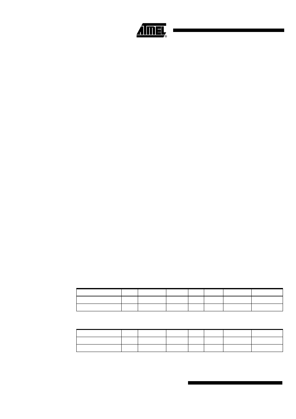
the following voltages or states can be measured at the pins WD_OSC, TEMP, INH, RXD and
LIN:
Table 1-2.
ATA6621
Mode
VCC
WD_OSC
TEMP
INH
RXD
LIN
Transceiver
Pre-normal mode
5V
2.5V
~2V
-
5V
Recessive
Off
Normal mode
5V
2.5V
~2V
-
5V
Recessive
On
Table 1-3.
ATA6622
Mode
VCC
WD_OSC
TEMP
INH
RXD
LIN
Transceiver
Fail Safe mode
3.3V
1.23V
-
On
3.3V
Recessive
Off
Normal mode
3.3V
1.23V
-
On
3.3V
Recessive
On