The development board in a simple application – Rainbow Electronics ATA6626 User Manual
Page 15
15
4970A–AUTO–01/07
ATA6621/22/24 Development Board
5.
The Development Board in a Simple Application
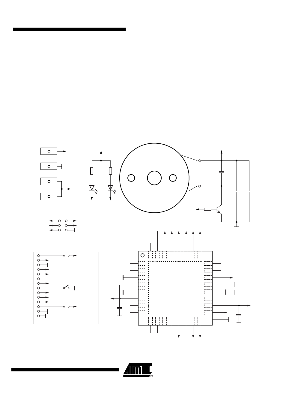
To show just how easy it is to develop a LIN-based application with the development board for
the ATA6621/22/24, here is a little example for a complete LIN slave node consisting of the
ATA6621 and the microcontroller ATmega88, a flasher controlled via the LIN bus.
The LIN interface of the slave is implemented with the ATA6621 and the control of the flasher
as well as the protocol handling is done by the ATmega88 microcontroller. In the schematic of
this slave node it is obvious that there are almost no other external components needed to ful-
fill the requirements of this application, other than the development board of the
ATA6621/22/24 and the ATmega88.
Figure 5-1.
Simple Application Using the Development Board for the ATA6621/22/24 (Schematic)
9
10
11
13
12
32
31
30
28
20
21
22
23
24
5
4
3
2
1
29
14
27
15
26
16
25
19
6
18
7
17
8
ATMEGA88
U1
PD3
PB1
PB2
PB3
PB4
PD5
PD6
PD7
PB0
PC5
PC4
PC3
PC2
PD2
PD1
PD0
PC6/NRST
PD4
GND (3)
VCC (4)
GND (5)
VCC (6)
PB6
PB7
PC1
PC0
ADC7
TXD
LED2
Flasher
NTRIG
RXD
EN
LED1
NRES
GND (21)
TEMP
PB1
PB4
PB3
PVCC
PVCC
VS
PVCC
JP1
PB5
AREF
ADC6
AVCC
PB5
GND (33)
PVCC
VS
X7
X6
X5
X4
LIN
VS
R5
XL2
XL1
1 k
Ω
+
+
100 µF
C8
10 µF
C7
100 nF
PB1
T1
C6
100 nF
C4
100 nF
C5
BC817-40
R2
330
Ω
R1
LED
LED
LED1
XISP1
ISP
LED2
D2
D1
330
Ω
100 nF
C1
MLF 5 mm
×
5 mm
0.5 mm pitch
32 lead
PVCC
PB4
PB3
PB5
NRES
RXD
TXD
X1
LIN
NTRIG
NRES
Development board
ATA6621/6622/6624
EN
S1
JP2
TEMP