6 unpowered mode, Table 4-3 – Rainbow Electronics ATA6631 User Manual
Page 12
12
9165A–AUTO–11/09
ATA6629/ATA6631
A wake-up event from either Silent or Sleep Mode will be signalled to the microcontroller using
the two pins RXD and TXD. The coding is shown in
.
A wake-up event will lead the IC to the Fail-safe Mode.
4.6
Unpowered Mode
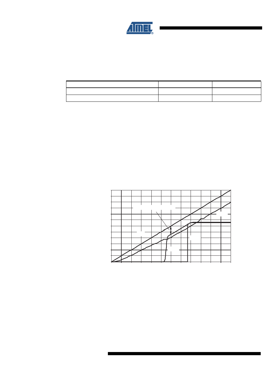
If you connect battery voltage to the application circuit, the voltage at the VS pin increases
according to the block capacitor (see
). After VS is higher than the VS
undervoltage threshold VS
th
, the IC mode changes from Unpowered Mode to Fail-safe Mode.
The VCC output voltage reaches its nominal value after t
VCC
. This time, t
VCC
, depends on the
VCC capacitor and the load.
The NRES is low for the reset time delay t
reset
. During this time, t
reset
, no mode change is
possible.
IF VS drops below VS
th
, then the IC switches to Unpowered Mode. The behaviour of VCC,
NRES and LIN is shown in
.
Figure 4-8.
VCC versus VS for the VCC = 3.3V Regulator
Table 4-3.
Signalling Fail-safe Sources
Fail-safe Sources
TXD
RXD
LIN wake up (pin LIN)
Low
Low
VS
th
(battery) undervoltage detection
High
Low
0 .0
0 .5
1.0
1.5
2 .0
2 .5
3 .0
3 .5
4 .0
4 .5
5.0
5.5
6 .0
0 .0
0 .5
1.0
1.5
2 .0
2 .5
3 .0
3 .5
4 .0
4 .5
5.0
5.5
6 .0
VS in V
V in V
VCC
LIN
NRES
VS
Regulator drop voltage V
D