Rainbow Electronics ATMOS™ 2M60 User Manual
Page 9
9
5440A–IMAGE–10/05
[Preliminary] ATMOS -2M60/2M30
• Readout of frame N. The readout data is forwarded to the Camera Link interface (FVAL
active) starting with the first line
• Readout of dummy frames (to prevent against large dark current integration) while the
camera waits for the next trigger event
The trigger delay is a few µs. The minimum pulse duration is 1 µs. The edge of trigger is pro-
grammable. The source of trigger is selectable between Camera Link CC1 signal and TTL_IO
trigger input. The period is defined by the programmable shutter time + readout time + wait.
Therefore the minimum period is reduced to 1 × readout time. As the integration time is not the
same for all lines (in the following timing diagram line n integration time is greater than line 1
integration time) this mode must be used with a pulsed light source or a shutter element. More-
over any residual light when shutter output signal is inhibited must be avoided. The exposure
time is defined by the shutter time and all the lines are exposed during the same time.
See register Aperture Shutter Time @ 246H Internal Register Mapping on
Figure 4-4.
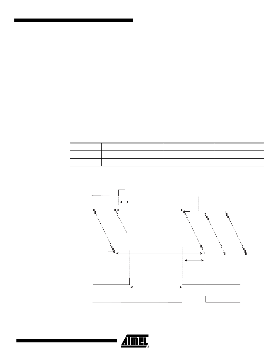
Triggered Mode Without Full Reset Chronogram
Table 4-3.
Shutter Time Values at Triggered Mode without Full Reset
Label
Description
2M60
2M30
Tsh
Maximum shutter time (ms)
655
1310
T1
Step duration (µs)
10
20
Line1 Reset
Line 1
Integration
(Frame N)
Frame N
Readout
Line n
Integration
(Frame N)
Line n Reset
Line 1 Readout
and Reset
Trigger N Event
Trigger In
Programmable
Shutter Time
Shutter out
Trigger Delay
FVA
L
Line n Readout
and Reset