4 serial communication, 1 internal register, G on – Rainbow Electronics ATMOS™ 2M60 User Manual
Page 16
16
5440A–IMAGE–10/05
ATMOS -2M60/2M30 [Preliminary]
6.4
Serial Communication
The Camera Link interface provides two LVDS signal pairs for the communication between the
camera and the frame grabber. This is an asynchronous serial communication based on RS-232
protocol.
The configuration of the serial line is:
• Full duplex/without handshaking
• 8-bit data, no parity bit, 1 stop bit
• 9600 bauds at power up, then programmable up to 115200 bauds (see register
Communication Speed Multiplieur @ 001H, Internal Register Mapping on
.
6.4.1
Internal Register
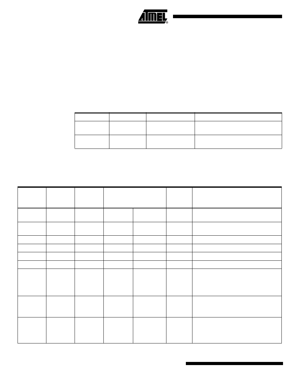
Table 6-5.
Camera Link Serial Communication Description
Signal Name
I/O
Type
Description
SerTFG
O
RS644
Differential pair for serial communication
to the frame grabber
SerTC
I
RS644
Differential pair for serial communication
from the frame grabber
Table 6-6.
Internal Register Mapping
Start Addr
(Hex)
Size (Dec)
End
Addr (Hex)
Access Type
Processing Internal Task
Factory
Settings
Description
000
1
RO
RO
Synchronization register for serial
communication (value 00)
001
1
RW
-
1
Communication speed multiplier (9600 -
115,2K): volatile register 1, 2, 3, 4, 6, 8, 12
040
51
RO
-
Hardware identifier
080
8
RO
-
Firmware identifier
0C0
51
RW
-
User identifier
100
4
RW
RW
Status (ref. Camera Status Management)
104
4
WO
-
Lock/Unlock mode: advanced user/user
1: Lock advanced user mode
(into user mode)
Unlock key value: unlock user
108
1
RO
-
Privilege level
1: Advanced user mode
2: User mode
109
1
WO
-
Current configuration save in Eeprom
1: User settings (allowed only for advanced
user mode)
2 to 4: User settings