On-chip rc oscillator, Figure 2, Figure 3 – Rainbow Electronics AT90S1200 User Manual
Page 4
4
AT90S1200
0838H–AVR–03/02
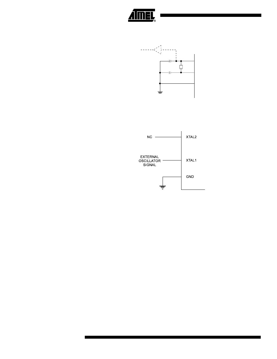
Figure 2. Oscillator Connections
Note:
When using the MCU Oscillator as a clock for an external device, an HC buffer should be
connected as indicated in the figure.
Figure 3. External Clock Drive Configuration
On-chip RC Oscillator
An On-chip RC Oscillator running at a fixed frequency of 1 MHz can be selected as the
MCU clock source. If enabled, the AT90S1200 can operate with no external compo-
nents. A control bit (RCEN) in the Flash Memory selects the On-chip RC Oscillator as
the clock source when programmed (“0”). The AT90S1200 is normally shipped with this
bit unprogram med (“1”). Parts with this bit progra mmed can be ord ered as
AT90S1200A. The RCEN-bit can be changed by parallel programming only. When
using the On-chip RC Oscillator for Serial Program downloading, the RCEN bit must be
programmed in Parallel Programming mode first.
XTAL2
XTAL1
GND
C2
C1
MAX 1 HC BUFFER
HC
- MAX5151 (16 pages)
- MAXQ3108 (64 pages)
- MAX5661 (39 pages)
- MAX6691 (7 pages)
- MAX5362 (12 pages)
- ADC10158 (26 pages)
- MAX8922L (14 pages)
- MAX8596Z (8 pages)
- MAX7491 (18 pages)
- MAX15040 (15 pages)
- MAX5177 (16 pages)
- ADC08138 (22 pages)
- MAX5961 (42 pages)
- T89C51RD2 (86 pages)
- MAX16055 (9 pages)
- MAX6659 (17 pages)
- ADC0820 (20 pages)
- MAX6678 (19 pages)
- MAX8884Z (15 pages)
- MAX16915 (9 pages)
- MAX8620 (18 pages)
- MAX5144 (12 pages)
- MAX6670 (8 pages)
- MAX8760 (39 pages)
- W78C32C (14 pages)
- MX7533 (8 pages)
- MAX8727 (13 pages)
- MAX9053 (15 pages)
- W78C54 (16 pages)
- MAX8614B (15 pages)
- W90N740 (219 pages)
- MAX6626 (13 pages)
- ADC10738 (30 pages)
- MAX17000 (31 pages)
- MAX5051 (21 pages)
- MAXQ1004 (18 pages)
- MAX6871 (51 pages)
- MX7847 (12 pages)
- MAX6608 (6 pages)
- MAX17083 (15 pages)
- MAX6641 (17 pages)
- MAX5251 (16 pages)
- MAX6338 (8 pages)
- MAX6690 (16 pages)
- MAX8668 (18 pages)