Watchdog timer, Watchdog timer control register – wdtcr – Rainbow Electronics AT90S1200 User Manual
Page 23
23
AT90S1200
0838H–AVR–03/02
Watchdog Timer
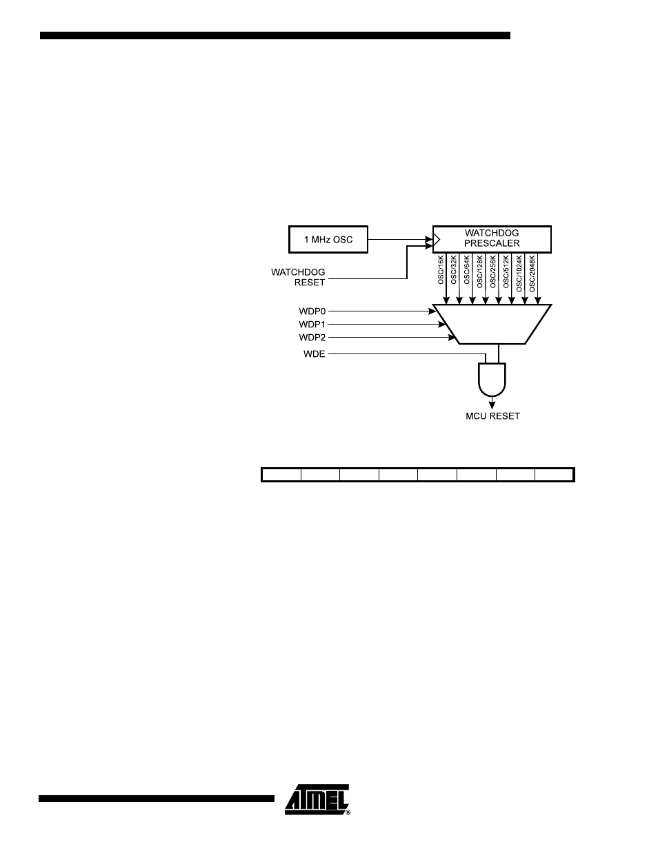
The Watchdog Timer is clocked from a separate On-chip Oscillator that runs at 1 MHz.
This is the typical value at V
CC
= 5V. See characterization data for typical values at other
V
CC
levels. By controlling the Watchdog Timer prescaler, the Watchdog Reset interval
can be adjusted, see Table 6 for a detailed description. The WDR (Watchdog Reset)
instruction resets the Watchdog Timer. Eight different clock cycle periods can be
selected to determine the maximum period between two WDR instructions to prevent
the Watchdog Timer from resetting the MCU. If the reset period expires without another
WDR instruction, the AT90S1200 resets and executes from the Reset Vector. For timing
details on the Watchdog Reset, refer to page 14.
Figure 20. Watchdog Timer
Watchdog Timer Control
Register – WDTCR
• Bits 7..4 – Res: Reserved Bits
These bits are reserved bits in the AT90S1200 and will always read as zero.
• Bit 3 – WDE: Watchdog Enable
When the WDE is set (one) the Watchdog Timer is enabled, and if the WDE is cleared
(zero) the Watchdog Timer function is disabled.
• Bits 2..0 – WDP2..0: Watchdog Timer Prescaler 2, 1 and 0
The WDP2..0 determine the Watchdog Timer prescaling when the Watchdog Timer is
enabled. The different prescaling values and their corresponding timeout periods are
shown in Table 6.
Bit
7
6
5
4
3
2
1
0
$21
–
–
–
–
WDE
WDP2
WDP1
WDP0
WDTCR
Read/Write
R
R
R
R
R/W
R/W
R/W
R/W
Initial Value
0
0
0
0
0
0
0
0